Installation and commissioning PlasmaQuant 9100 (Elite)
38
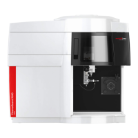
Figure21Control PC connection via hub
1 USB cable connections from the
sampler, dilution system, etc.
2 Hub
3 USB cable to the PC 4 Hub power supply
} Connect the sampler and the dilution system with each other and the emission spec-
trometer via the following hoses:
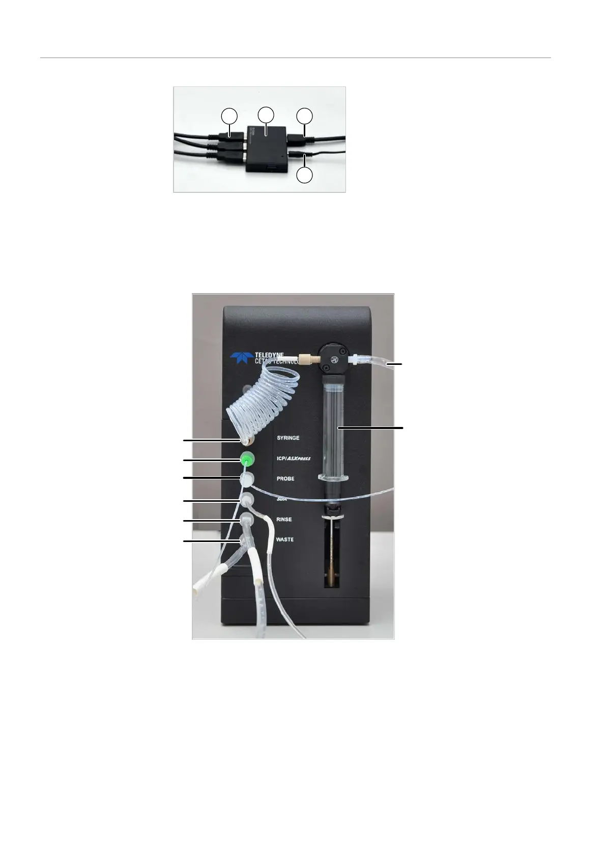
Figure22Hose connections on the dilution system
1 Diluent storage bottle connection 2 Syringe pump
3 Waste bottle connection 4 Purge liquid storage bottle connec-
tion (for vortexer mixing vessel)
5 Vortexer mixing vessel connection
(placed on the sampler)
6 Sampler syringe connection
7 Emission spectrometer sample hose
connection (via hose pump and
nebulizer)
8 Syringe pump connection (via hose
loop)