PlasmaQuant 9100 (Elite) Installation and commissioning
39
Coupling the sampler and the
dilution system with the
switching valve
} Connect the sampler and the dilution system as described.
} Connect the sampler with the switching valve control unit via the RS 232interface
(COM 1).
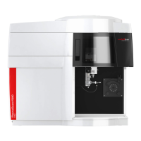
} Connect the following on the switching valve control unit:
Figure23Connecting the switching valve control unit
Connections on the rear of the sampler:
1 RS 232 interface (COM 1) to the control unit
Connections on the rear of the switching valve control system:
2 RS 232 interface to the sampler 3 Control unit power supply
4 USB to the PC (via hub) 5 Interface to the switching valve
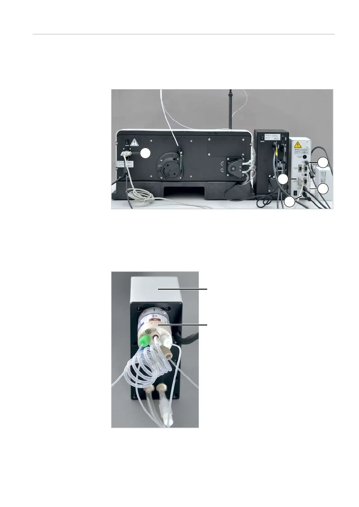
Figure24Connecting the hoses to the switching valve
1 Switching valve 2 6-port valve with labeled hose con-
nections