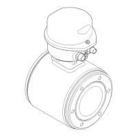
Proline Promag P 100
32 Endress+Hauser
Pulse/frequency output
Temperature coefficient Max. ±50 ppm o.r./100 °C
Installation
No special measures such as supports are necessary. External forces are absorbed by the construction
of the device.
Mounting location
Preferably install the sensor in an ascending pipe, and ensure a sufficient distance to the next pipe
elbow: h ≥ 2 × DN
A0017061
To prevent measuring errors arising from accumulation of gas bubbles in the measuring tube, avoid
the following mounting locations in the pipe:
• Highest point of a pipeline.
• Directly upstream of a free pipe outlet in a down pipe.
Installation in down pipes
Install a siphon or a vent valve downstream of the sensor in down pipes whose length h ≥
5 m (16.4 ft). This precaution is to avoid low pressure and the consequent risk of damage to the
measuring tube. This measure also prevents the system losing prime, which could cause air pockets.
For information on the liner's resistance to partial vacuum (→ 39)
A0017064
19 Installation in a down pipe
1 Vent valve
2 Pipe siphon
h Length of down pipe
Installation in partially filled pipes
A partially filled pipe with a gradient necessitates a drain-type configuration. The empty pipe
detection (EPD) function offers additional protection by detecting empty or partially filled pipes.
• Do not install the sensor at the lowest point in the drain: risk of solids accumulating.
• It is advisable to install a cleaning valve.

 Loading...


