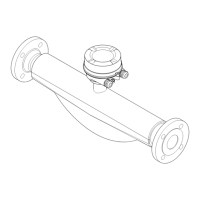
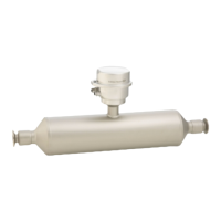
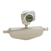
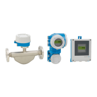
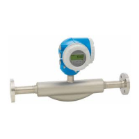
Proline Promass E 100 Modbus RS485 Electrical connection
Endress+Hauser 25
Connecting cable between Safety Barrier Promass 100 and measuring device
Cable type Shielded twisted-pair cable with 2x2 wires. When grounding the cable shield,
observe the grounding concept of the plant.
Maximum cable resistance 2.5 Ω, one side
Comply with the maximum cable resistance specifications to ensure the operational
reliability of the measuring device.
The maximum cable length for individual wire cross-sections is specified in the table
below. Observe the maximum capacitance and inductance per unit length of the cable and
the connection values in the Ex documentation .
Wire cross-section Maximum cable length
[mm
2
] [AWG] [m] [ft]
0.5 20 70 230
0.75 18 100 328
1.0 17 100 328
1.5 16 200 656
2.5 14 300 984
Cable diameter
• Cable glands supplied:
M20 × 1.5 with cable ⌀ 6 to 12 mm (0.24 to 0.47 in)
• Spring terminals:
Wire cross-sections 0.5 to 2.5 mm
2
(20 to 14 AWG)
• With Safety Barrier Promass 100:
Plug-in screw terminals for wire cross-sections0.5 to 2.5 mm
2
(20 to 14 AWG)
7.2.3 Terminal assignment
Transmitter
Modbus RS485 connection version
For use in the non-hazardous area and Zone 2/Div. 2
Order code for "Output", option M
Depending on the housing version, the transmitters can be ordered with terminals or
device plugs.
Order code
"Housing"
Connection methods available
Possible options for order code
"Electrical connection"
Output
Power
supply
Options
A, B
Terminals Terminals • Option A: coupling M20x1
• Option B: thread M20x1
• Option C: thread G ½"
• Option D: thread NPT ½"
Options
A, B
Device plugs
→ 28
Terminals • Option L: plug M12x1 + thread NPT ½"
• Option N: plug M12x1 + coupling M20
• Option P: plug M12x1 + thread G ½"
• Option U: plug M12x1 + thread M20

 Loading...


