Proline Promass E 100 Modbus RS485 Electrical connection
Endress+Hauser 33
Modbus RS485 intrinsically safe
21
A
B
3
A
B
L+
L-
L- L+
A
B
5 6 7
4
8
A
B
L+
L-
A0028766
16 Connection example for Modbus RS485 intrinsically safe
1 Control system (e.g. PLC)
2 Cable shield provided at one end. Observe cable specifications
3 Safety Barrier Promass 100
4 Observe cable specifications
5 Non-hazardous area
6 Non-hazardous area and Zone 2/Div. 2
7 Intrinsically safe area
8 Transmitter
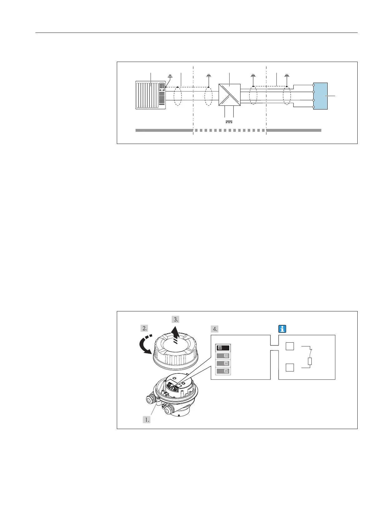
7.5 Hardware settings
7.5.1 Enabling the terminating resistor
Modbus RS485
To avoid incorrect communication transmission caused by impedance mismatch, terminate
the Modbus RS485 cable correctly at the start and end of the bus segment.
If the transmitter is used in the non-hazardous area or Zone 2/Div. 2
2 - Not used
1 - Write protection
4 - Bus termination
3 - Not used
OFFON
26
27
A
B
220 W
A0017610
17 Terminating resistor can be enabled via DIP switch on the main electronics module