6.2 Deep well monitoring
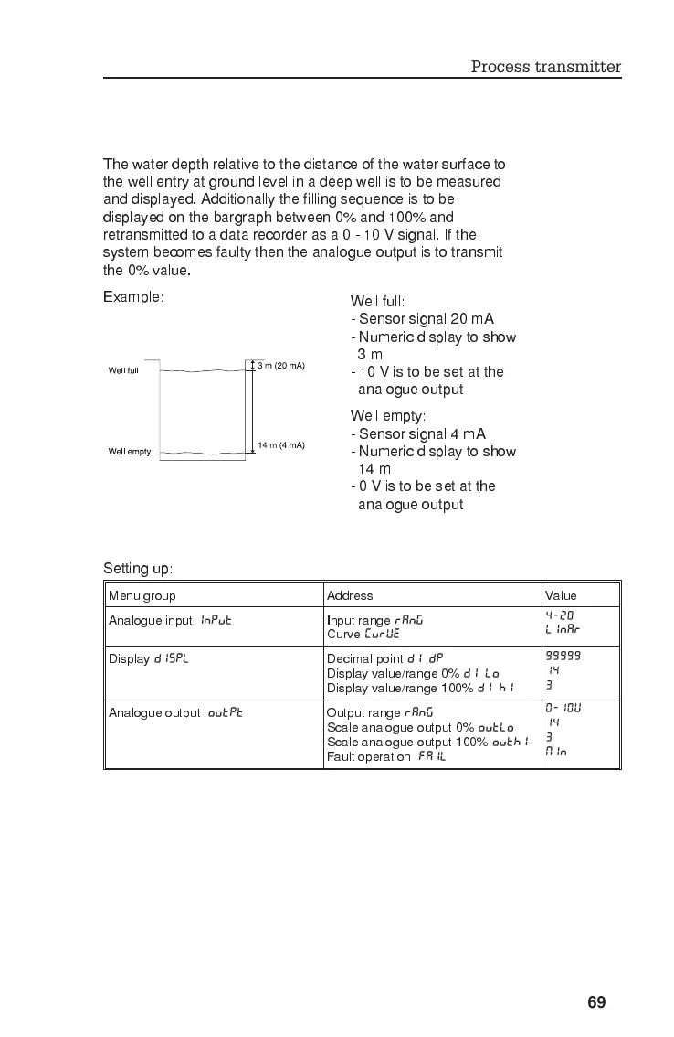
The water depth relative to the distance of the water surface to
the well entry at ground level in a deep well is to be measured
and displayed. Additionally the filling sequence is to be
displayed on the bargraph between 0% and 100% and
retransmitted to a data recorder as a 0 - 10 V signal. If the
system becomes faulty then the analogue output is to transmit
the 0% value.
Example:
Setting up:
Menu group Address Value
Analogue input
INPUT
Input range
RANG
Curve
CURVE
4-20
LINAR
Display
DISPL
Decimal point
DI DP
Display value/range 0%
DI LO
Display value/range 100%
DI HI
99999
14
3
Analogue output
OUTPT
Output range
RANG
Scale analogue output 0%
OUTLO
Scale analogue output 100%
OUTHI
Fault operation
FAIL
0-10V
14
3
MIN
Well full:
- Sensor signal 20 mA
- Numeric display to show
3m
- 10 V is to be set at the
analogue output
Well empty:
- Sensor signal 4 mA
- Numeric display to show
14 m
-0Vistobesetatthe
analogue output
Process transmitter
69