4. Operating overview
Depending on the version and application, the unit offers the
user a large number of possible settings and software
functions. Please take note of the following paragraphs
relating to the operation. Hints for setting up the unit are valid
for an unit including all options. Therefore there could be slight
differences between these and the unit in your possession. In
particular paragraphs 4.3 and 4.4 explaining the display and
use of the operating menu is only valid for an unit with the
LC display with front end operation option.
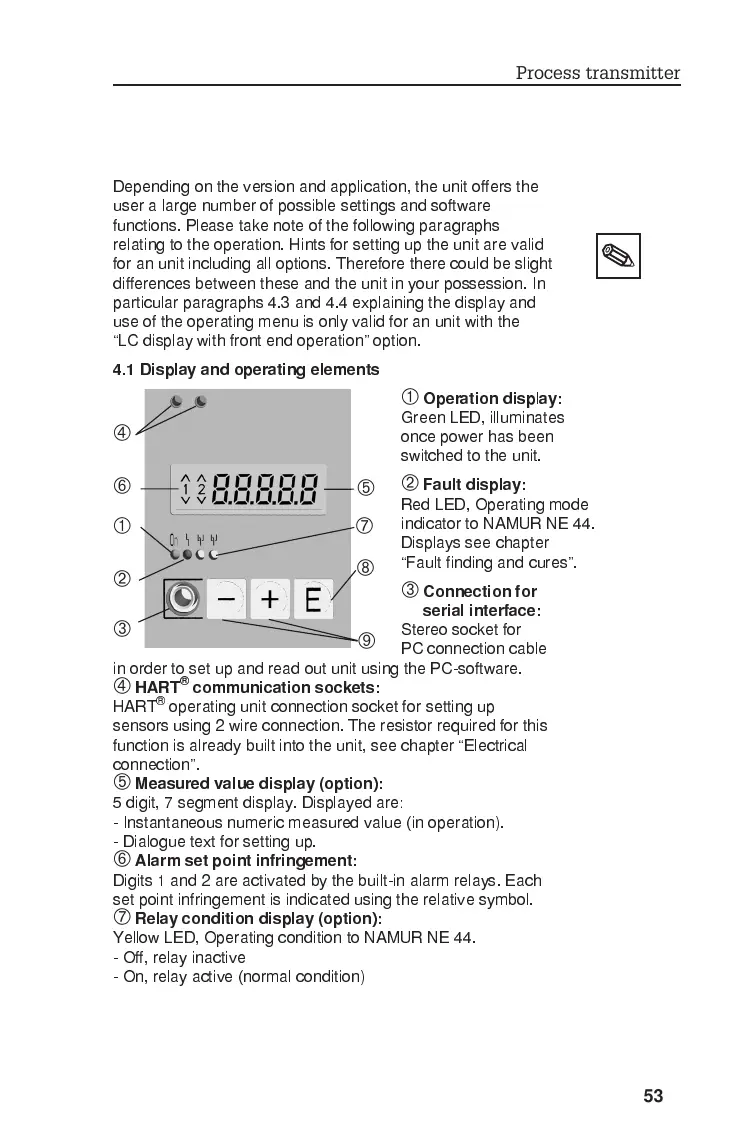
4.1 Display and operating elements
À
Operation disp
l
ay:
Green LED, illuminates
once power has been
switched to the unit.
Á
Fault display:
Red LED, Operating mode
indicator to NAMUR NE 44.
Displays see chapter
Fault finding and cures.
Â
Connection for
serial interface:
Stereo socket for
PC connection cable
in order to set up and read out unit using the PC-software.
Ã
HART
®
communication sockets:
HART
®
operating unit connection socket for setting up
sensors using 2 wire connection. The resistor required for this
function is already built into the unit, see chapter Electrical
connection.
Ä
Measured value display (option):
5 digit, 7 segment display. Displayed are:
- Instantaneous numeric measured value (in operation).
- Dialogue text for setting up.
Å
Alarm set point infringement:
Digits 1 and 2 are activated by the built-in alarm relays. Each
set point infringement is indicated using the relative symbol.
Æ
Relay condition display (option):
Yellow LED, Operating condition to NAMUR NE 44.
- Off, relay inactive
- On, relay active (normal condition)
À
Á
Å
Ä
Â
Ã
Æ
Ç
È
Process transmitter
53