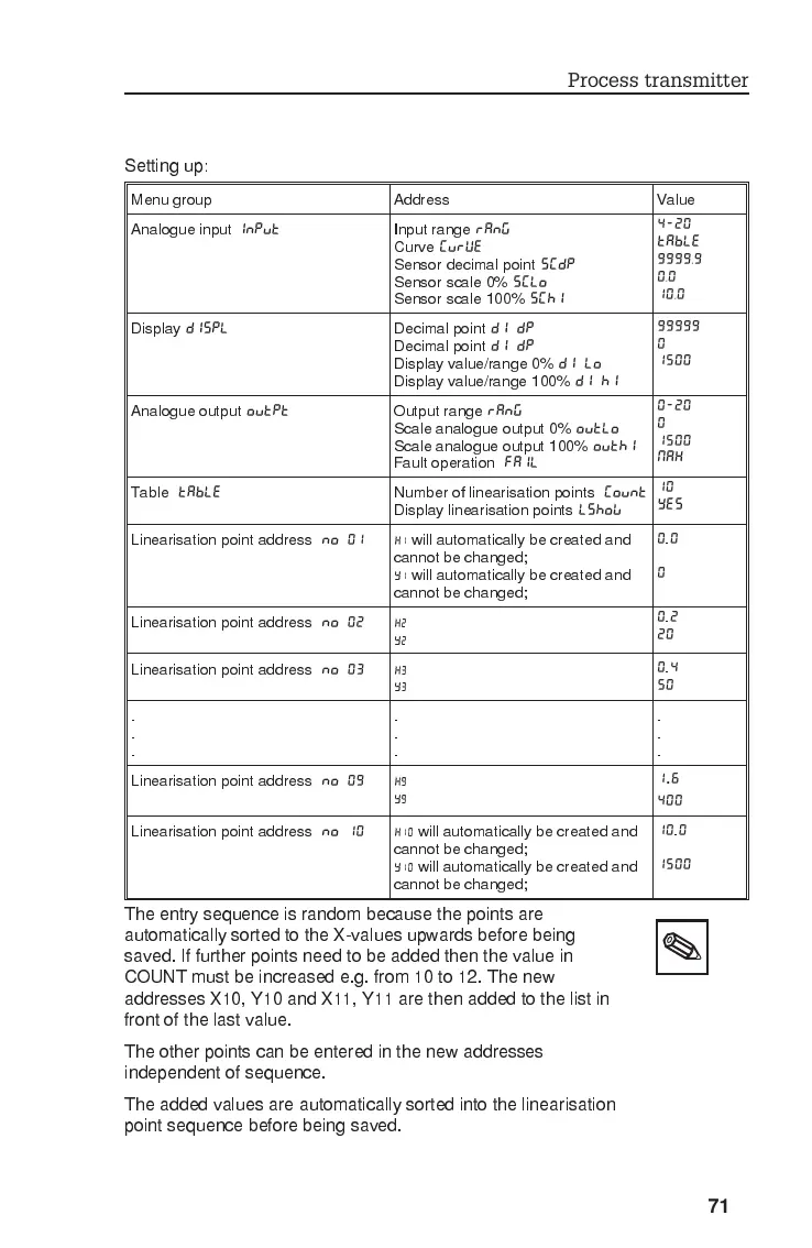
Setting up:
The entry sequence is random because the points are
automatically sorted to the X-values upwards before being
saved. If further points need to be added then the value in
COUNT must be increased e.g. from 10 to 12. The new
addresses X10, Y10 and X11, Y11 are then added to the list in
front of the last value.
The other points can be entered in the new addresses
independent of sequence.
The added values are automatically sorted into the linearisation
point sequence before being saved.
Menu group Address Value
Analogue input
INPUT
Input range
RANG
Curve
CURVE
Sensor decimal point
SCDP
Sensor scale 0%
SCLO
Sensor scale 100%
SCHI
4-20
TABLE
9999,9
0,0
10,0
Display
DISPL
Decimal point
DI DP
Decimal point
DI DP
Display value/range 0%
DI LO
Display value/range 100%
DI HI
99999
0
1500
Analogue output
OUTPT
Output range
RANG
Scale analogue output 0%
OUTLO
Scale analogue output 100%
OUTHI
Fault operation
FAIL
0-20
0
1500
MAX
Table
TABLE
Number of linearisation points
COUNT
Display linearisation points
LSHOW
10
YES
Linearisation point address
NO 01
X1
will automatically be created and
cannot be changed;
Y1
will automatically be created and
cannot be changed;
0
.
0
0
Linearisation point address
NO 02
X2
Y2
0
.
2
20
Linearisation point address
NO 03
X3
Y3
0
.
4
50
.
.
.
.
.
.
.
.
.
Linearisation point address
NO 09
X9
Y9
1.6
400
Linearisation point address
NO 10
X10
will automatically be created and
cannot be changed;
Y10
will automatically be created and
cannot be changed;
10
.
0
1500
Process transmitter
71