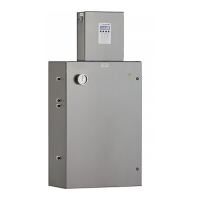
SS500/SS2000 Analyzer
3–8 4900002285 rev. B 3-25-20
Toconnecttheoutputsignals
1. Disconnect power to the analyzer and open the electronics enclosure
cover. Take care not to disturb the electrical assembly inside.
2. Run conduit from the signal/alarm receiving station to the conduit
hub on the electronics enclosure labeled for signal connections.
3. Route the customer-supplied cable(s) for the current loop(s) and
digital output relays through the conduit into the electronics
enclosure.
4. Strip back the jacket and insulation of the current loop, digital output
relays and serial cables (shown in Figure 1–4 or Figure 1–7) just
enough to connect to the mating terminal block (TB2), shown in
Figure 3–4. The mating terminal block can be pulled up and removed
from its base to make the cable connection process easier.
5. Connect the 4-20 mA current loop signal wires to the appropriate
terminals, as indicated in Table 3–1.
6. Connect the serial cable wires to the appropriate terminals according
to Table 3–1. For reference, Table 3–1 also shows the corresponding
pin numbers for configuring a nine-pin Sub-D connector for
connection to a computer serial port.
Interconnect cables shall not exceed the following parameters:
• The maximum allowed inductance to resistance ratio (L/R ratio)
must be less than 25 microhenry/ohm.
• The maximum total loop capacitance shall be 0.27 microfarads.
Conduit seals should be used where appropriate in compliance
with local regulations.
Figure 3–4 Mating terminal block (TB2) in
electronics enclosure for connecting signal cables
121110987654321
TB2

 Loading...


