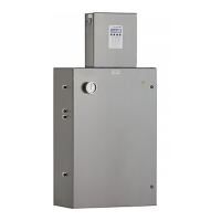
SS500/SS2000 Analyzer
3–12 4900002285 rev. B 3-25-20
Toconnectthesamplesupplyline
1. First, confirm that the sample probe is correctly installed at the
process supply tap and that the sample probe isolation valve is
closed.
2. Also, confirm that the field pressure reducing station is installed
properly at the sample probe and that the pressure regulator at the
field pressure reducing station is closed (adjustment knob turned
fully counter-clockwise).
3. Determine appropriate tubing route from the field pressure reducing
station to the sample conditioning system (SCS).
4. If configured with this analyzer, install the heat trace bundle in the
heat trace sample inlet.
a. Remove the white foam supplied with the SCS.
b. Run the entire heat trace bundle into the enclosure.
c. Once installed, seal the rubber tube around the heat trace by
applying heat until the tube shrinks down around the heat trace
bundle
.
5. If configured with this analyzer, install the heat trace terminal box
external to the SCS enclosure using the supplied GFI Heat Trace
Power conduit hub.
a. Run the heat trace power back out of the enclosure and into the
heat trace terminal box through the GFI Heat Trace Power
conduit hub.
Consult sample probe manufacturer instructions for proper
installation procedures.
The process sample at the sample tap may be at a high pressure.
Use extreme caution when operating the sample probe isolation
valve and field pressure reducing regulator.
All valves, regulators, switches, etc. should be operated in
accordance with site lock-out/tag-out procedures.
Hazardous voltage and risk of electric shock. Follow your
plant safety guidelines or refer to your safety engineer before
attempting to heat the rubber tube.

 Loading...


