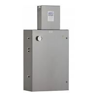
SS500/SS2000 Analyzer
3–10 4900002285 rev. B 3-25-20
4. For 4-20 mA sink, carefully replace the jumper to connect the center
hole with point “P.”
5. Repeat steps 2-4 as necessary for any remaining 4-20 mA boards.
6. Reconnect power to the analyzer. Confirm the 4 mA (min.) and
20 mA (max.) points. Close and tighten the electronics enclosure
cover. Follow the programming instructions below.
Calibratingtheanalogoutput
1. Connect a calibrator and digital multi-meter into the circuit.
2. On the analyzer keypad, press #2 (Mode 2), the password (3142)
and *.
3. Continue pressing the * key until the 4-20 mA % Test parameter
displays.
Needle nose pliers may be required to remove the jumper.
Figure 3–5 4-20 mA output board
JMP1
Potentiometers
<CHASETPARAMETER>
4‐20mA %Test
101
Entera %(101=Off)

 Loading...


