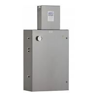
SS500/SS2000 Analyzer
iv 4900002285 rev. B 3-25-20
Figure B–1. Measurement cell types . . . . . . . . . . . . . . . . . . . . . . . . . . . . . . . B-4
Figure B–2. Stainless steel mirror marking . . . . . . . . . . . . . . . . . . . . . . . . . . B-4
Figure B–3. Stainless steel mirror - mirror side up . . . . . . . . . . . . . . . . . . . . . B-8
Figure B–4. SS500/SS2000 analyzer component locations . . . . . . . . . . . . . . . B-9
Figure B–5. Removed measurement cell with pressure sensor face up . . . . . . B-10
Figure B–6. Removing the old pressure sensor . . . . . . . . . . . . . . . . . . . . . . B-10
Figure B–7. Removing excess seal tape from flange . . . . . . . . . . . . . . . . . . . B-11
Figure B–8. Replacing seal tape . . . . . . . . . . . . . . . . . . . . . . . . . . . . . . . . . B-11
Figure B–9. Replacing pressure sensor . . . . . . . . . . . . . . . . . . . . . . . . . . . . B-12
Figure B–10. Newly installed pressure sensor positioning . . . . . . . . . . . . . . . . B-12
Figure B–11. Setting/locking the needle valve . . . . . . . . . . . . . . . . . . . . . . . . B-14
Figure B–12. Inspecting the membrane separator filter . . . . . . . . . . . . . . . . . B-15
Figure B–13. Disconnecting the rotameter . . . . . . . . . . . . . . . . . . . . . . . . . . B-16
Figure B–14. Stabilizing the rotameter for removal . . . . . . . . . . . . . . . . . . . . B-16

 Loading...


