Chapter 6 Troubleshooting & Repairs
Adjust the sensors to protect these components. The following table describes the locations of the
prox
imity sensors:
TABLE 6-2. Proximity Sensor Locations
Component
Proximity Sensor Location
Clearance
Can flattener
Above gear
¾ turn
PET flattener
Above gear
¾ turn
Sorting
Rear of cylinder
½" from plate
1.
Gain access to the proximity sensor mounted on the compactor. See Table 6-
2 for the locations.
2.
Disconnect the sensor from the cable or extension cable.
3.
Loosen the nut that secures the sensor, and thread the sensor out of the holder.
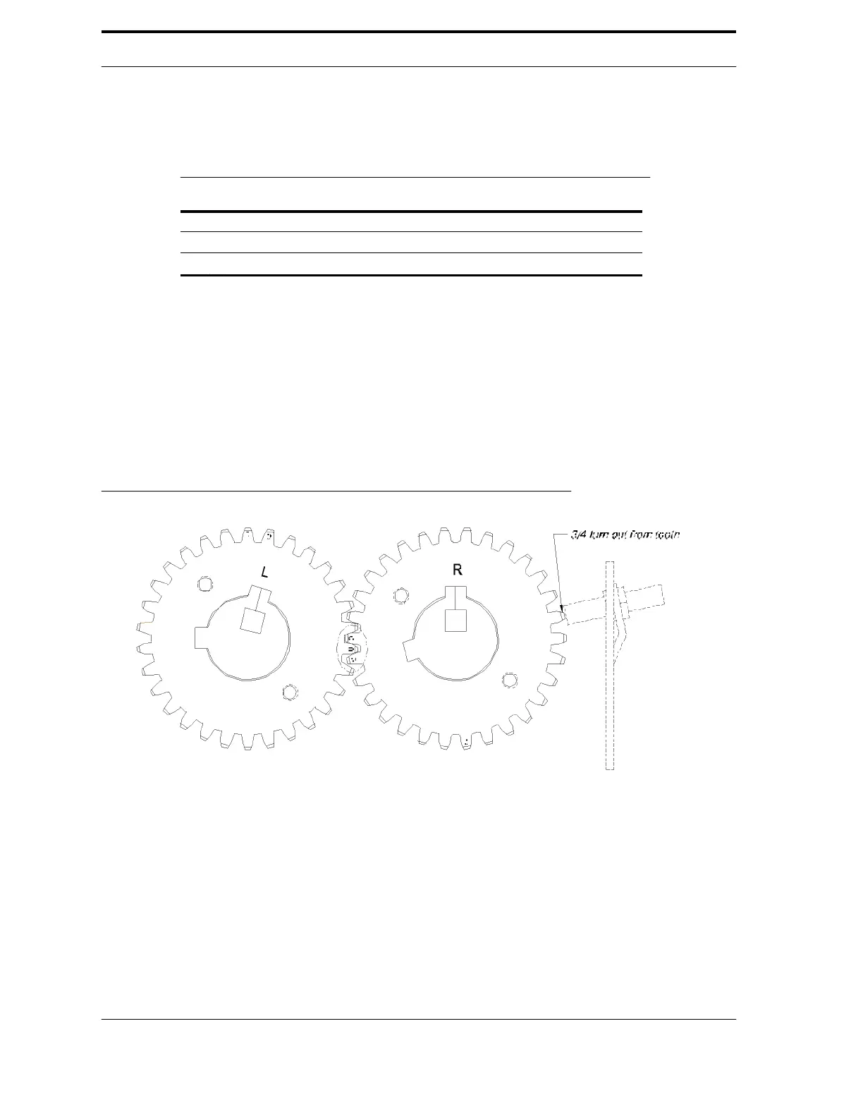
4.
Thread the replacement sensor into position until it makes contact with
either the gear tooth or the plate, whichever is applicable. Back out to the
appropriate clearance distance (see Table 6-2 and Figure 6-7).
5.
Firmly tighten the nut to secure the sensor. Do not over-tighten it.
FIGURE 6-7. Example of the sensor spacing on a gear
6-10