Chapter
4
•
••
• Selected Client
- Switches between the boards on the Multidrop Bus.
MC1 is found in the hexadecimal number range between 40 and 4F.
•
••
• FW Version
- Indicates the firmware version of the MC1 board.
•
••
• Actuators - Shows the options for MC1’s actuators. Tap on the Actuators
button to switch to Sensors or Thresholds.
•
••
• Safety Loop >> - Indicates whether the safety loop is intact, broken, or
overridden. The status may be one of the following:
•
••
• BRK indicates that the door is open.
•
••
• OK indicates that the loop is intact.
•
••
• OVR indicates that the interlock is overridden by the service key.
•
••
• Increase Counter - Increases the mechanical counter by one.
•
••
• Compactor Actuators - The Forward and Reverse buttons are gray by
default. To activate these buttons, insert and turn the interlock override key, and
then press the forward button. An info screen will appear with a button to run
the compactor. The compactor will start as soon as the button is pressed.
•
••
• Stall Sensor Adjustment - Click on the box in front of Stall Sensor Adjustment
to activate this feature for testing. Once activated, turn on the compactor Forward to
view the Hertz and Duty Cycle. The Duty Cycle should read between 55
and 60%. Adjust the compactor proximity switch if needed.
Warning!
Use extreme caution when operating a compactor with the doors open.
Keep your body and loose clothing away from moving parts.
•
••
• Camera Light 1 & Camera Light 2 - Toggle power to the camera lights.
•
••
• Relay 1 & Relay 2 - Toggle power to the relays.
•
••
• Button Lights - Not used.
4.4.4.
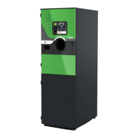
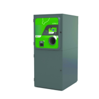
Ultra-48 Tab
The Ultra-48 tab is shown in Figure 4-10. The default screen shows the options for the Actuators.
Tap on Actuators to see the options for Sensors and Thresholds. The Ultra-48 actuators are
controlled by the MC5/MD5 boards. See Figure 4-11 to see where these components are located.
See Section 4.5 “Sensors and Thresholds” on page 4-17 for information about sensors and
thresholds.