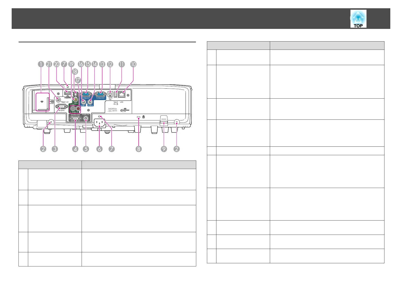
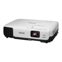
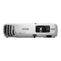
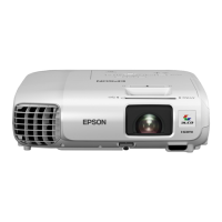
Rear
Name Function
A
Wireless LAN unit
installation section
Install the optional Wireless LAN unit here. Remove the
stopper when installing.
s "Installing the Wireless LAN Unit" p.27
B
Screw holes to fix the
cable cover
Screw holes to fix the cable cover in place.
s "Attaching and Removing the Cable Cover" p.27
C
RS-232C port
When controlling the projector from a computer, connect
it to the computer with an RS-232C cable. This port is for
control use and should not normally be used.
s "ESC/VP21 Commands" p.118
D
Monitor Out port
Outputs analog RGB signals input from the Computer1
port to an external monitor. You cannot output signals
input from other ports or component video signals.
E
Audio Out port
Outputs the sound of the image currently being projected
to external speakers.
Name Function
F
Power inlet
Connects the power cable to the projector.
s "From Installation to Projection" p.30
G
Cable Holder
Insert the supplied cable clamp here to prevent the HDMI
and power cables from falling out.
See the following for more details on the installation
procedure.
s Quick Start Guide
H
Security slot
The security slot is compatible with the Microsaver
Security System manufactured by Kensington.
s "Anti-Theft Lock" p.60
I
Security cable
installation point
A commercially available theft-prevention wire lock can
be passed through the installation point to secure the
projector to a desk or pillar.
s "Anti-Theft Lock" p.60
J
LAN port
Connects a LAN cable to connect to a network.
K
USB (TypeA) port
• Connects a USB memory device or a digital camera, and
projects images as a Slideshow.
s
"Projecting Without a Computer (Slideshow)"
p.109
• Connects the optional Document Camera.
L
USB (TypeB) port
Connects the projector to a computer via the
commercially available USB cable to use the Wireless
Mouse function.
s "Using the Remote Control to Operate the Mouse
Pointer (Wireless Mouse)" p.50
M
Computer2 port
For analog RGB signals from a computer and component
video signals from other video sources.
N
Audio2 port
Inputs audio from equipment connected to the
Computer2 port.
O
Computer1 port
For analog RGB signals from a computer and component
video signals from other video sources.
Part Names and Functions
10