2. Installation
RC700 / RC90 Option Fieldbus I/O Rev.14 215
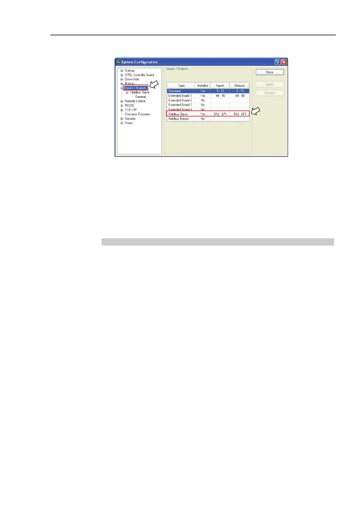
(6) Select [Setup]-[System Configuration] and display the [System Configuration] dialog
box.
(7) Select [Inputs / Outputs].
(8) Confirm that the following items are displayed in “Fieldbus slave”.
Inputs : 512 – ( 512 + Changed number of input (Bits)
Outputs : 512 – ( 512 + Changed number of output (Bits) )
In this example, Input byte is 20 bytes (160 bits) and 512-671 is displayed in Inputs.
Also, Output byte is 20 bytes (160 bits) and 512-671 is displayed in Outputs.
(9) Click <Close>.
Operations
When the CC-Link is installed, some operation differs from the other Fieldbus I/O options.
This section describes about these differences.
Remote Input
Remote input (RX) and remote output (RY) indicates ON/OFF information. Remote data
is bit data and the FROM/TO command is executed per 16 bits (1 word).
“n” in the following tables is address configured as a master station with the station
configure. This is calculated by the following expression.
n = (Station − 1) × 2
Result of the calculation is in decimal number. Substitute the result to “n” after converting
to hexadecimal number.
(Example)
When CC-Link board station is 1
Remote Input RXn0 to RX(n+5)F → RX00 to RX5F
Remote Output RYn0 to RY(n+5)F → RY00 to RY5F
When CC-Link board station is 4
Remote Input RXn0 to RX(n+5)F → RX60 to RXAF
Remote Output RYn0 to RY(n+5)F → RY60 to RYAF