SC-F9200 Series Revision B
DISASSEMBLY & ASSEMBLY Disassembly and Assembly Procedure 107
SE Group Confidential (Related Staff Only)
3.4.3.4 Right Front Cover
1. Remove the Media Loading Lever. (p210)
2. Remove the Panel Unit. (p101)
3. Remove the Right Upper Cover. (p103)
4. Remove the Ink Tank. (p207)
5. Remove the Lower Ink Holder. (p106)
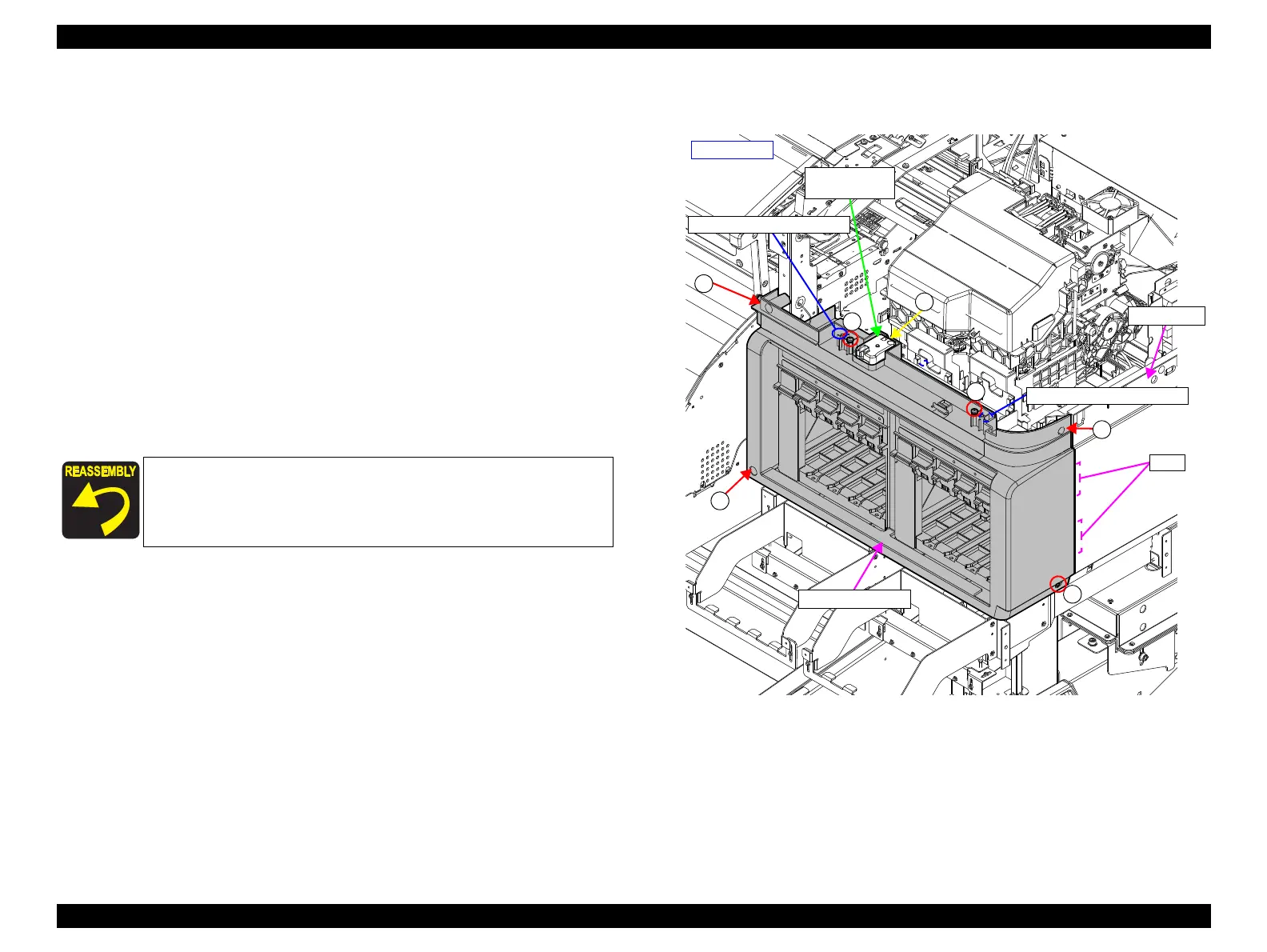
6. Remove the screw, and remove the R Maintenance Cover Sensor.
A) Silver M3x10 P-tite screw with washer: 1 pcs
7. Remove the six screws that secure the Right Front Cover.
B) Silver M4x10 S-tite screw with washer: 5 pcs
C) Silver M4x12 S-tite screw with washer: 1 pcs
8. Disengage the upper portion of the Right Front Cover from the dowels on the main
body frame, and remove the Right Front Cover.
Figure 3-26. Removing the Right Front Cover
Insert the two tabs of the Right Front Cover into the two
positioning holes on the Right Cover.
Align the two dowels of the frame with the two positioning
holes on the Right Front Cover.
B
B
B
C
A
B
B
R Maintenance
Cover Sensor
- Right side -
Positioning hole and dowel
Positioning hole and dowel
Tabs
Right Cover
Right Front Cover

 Loading...


