SC-F9200 Series Revision B
DISASSEMBLY & ASSEMBLY Disassembly and Assembly Procedure 241
SE Group Confidential (Related Staff Only)
3.4.8.5 ATC Motor
1. Remove the Roll Paper Holder of the Right Roll Unit. (p238)
2. Remove the Right Roll Side Cover.
(See Step 2 to Step 5 in
“3.4.8.4 Sub-F Board (Roll)” (P. 239))
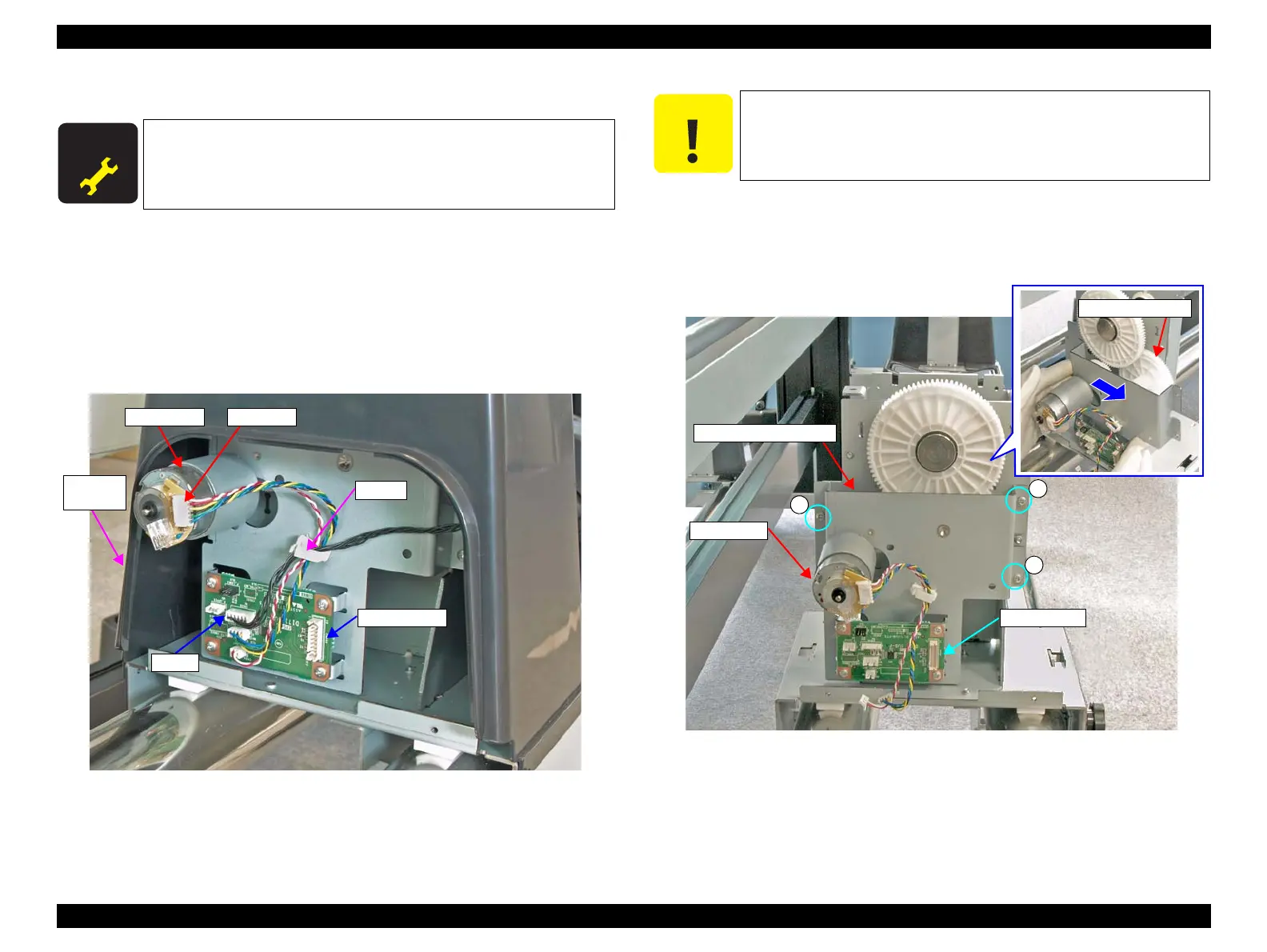
3. Disconnect the cable from the connector (CN606) on the Sub-F Board.
4. Release the cable from the clamp, and remove the Right Roll Cover.
5. Disconnect the cable from the connector of the ATC Motor.
Figure 3-195. Removing the Right Roll Cover
6. Remove the three screws that secure the Right Roll Side Frame.
A) M3x8 S-tite screw: 3 pcs
7. Slide the Right Roll Side Frame in the direction of the arrow to remove it.
Figure 3-196. Removing the Right Roll Side Frame
A D J U S T M E N T
R E Q U I R E D
When replacing/removing this part, refer to “4.1.2 Adjustment
Items and the Order by Repaired Part” (p260) and make sure to
perform the specified operations including required adjustment.
Clamp
Right Roll
Cover
Sub-F Board
CN606
ATC Motor Connector
Perform the next step while holding the Compound Gear with your
hand to prevent it from falling.
Right Roll Side Frame
Sub-F Board
ATC Motor

 Loading...


