EPSON Stylus COLOR 860/1160 Revision C
Operating Principles Electrical Circuit Operating Principles 45
2.2.2.1 Printhead Driver Circuit
The printhead driver circuit consists of the following two components:
n Common driver IC (IC10: E09A14RA) directly attached to the
C298MAIN board.
n Nozzle selector IC (Sharp IR2C95F or EPSON SED6125T0A) on the
head board.
The common driver (IC10: E09A14RA) generates a reference drive waveform
according to the output signals from the C298MAIN board. The reference drive
waveform is amplified by the transistors Q3 and Q4 and then transferred to the
nozzle selector IC on the head board. Print data is converted to serial data by
the ASIC (IC8 E05B70CD) and then sent to the nozzle selector IC on the head
board. Based on the serial data, the nozzle selector IC determines the nozzles
to be actuated. The selected nozzles are driven by the drive waveforms
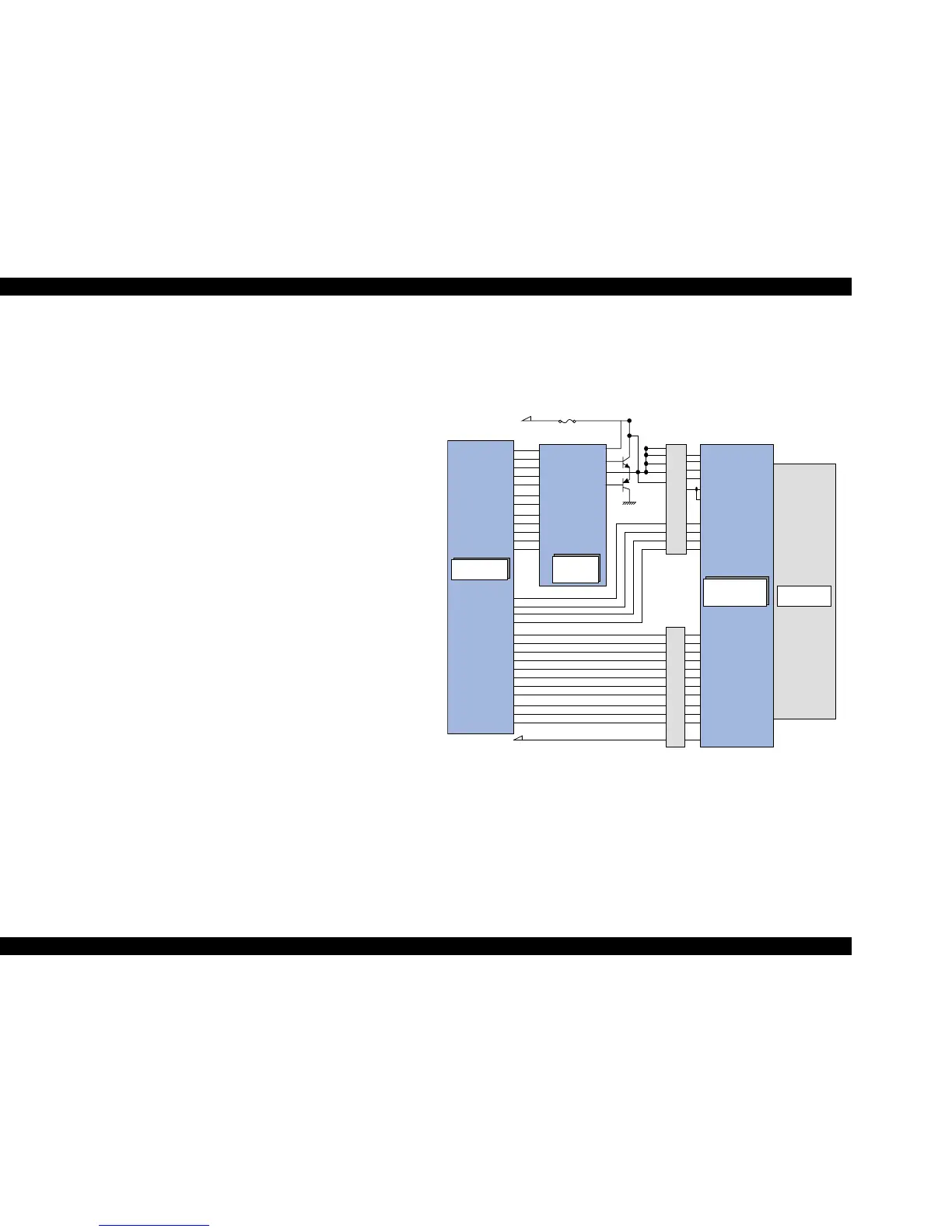
produced by the common driver. See Figure 2-17 for the printhead driver circuit
block diagram.
o Head common driver circuit
The reference head drive waveform is produced in the common driver
(IC10: E09A14RA) based on the following 12 signal lines output from the
ASIC (IC8 E05B70CD); A0-A4, CLK1, CLK2, RST, FLOOR, DATA, DCLK,
and E.
By the DATA signal output from the ASIC (IC8 E05B70CD), the original
data for the head drive waveform is written in the memory in the IC10. The
addresses for the written data are determined by the A0 - A4 signals, and,
of among, data used to determine the waveform angles is selected. Then,
setting the selected data, producing trapezoid waveform value, and
canceling the data are performed by the rising edges of the CLK1 and
CLK2 signals.
o Head nozzle selector circuit
Printing data is converted into serial data by the ASIC (IC8 E05B70CD).
Then the converted data is allocated to the six rows, the number of the
head nozzle rows, to be transferred to the nozzle selector (Sharp
IR2C95F) through the six signal lines (HS01 to HS06). Data transmission
from the ASIC (IC8 E05B70CD) to the nozzle selector synchronizes with
the LAT signal and SCK clock signal. Referring to the transferred data,
nozzles to be activated are selected, and the PZTs of the selected nozzles
are driven by the drive waveform output from the head common driver.
Figure 2-17. Printhead Driver Circuit
H ead D rive
P u ls e
AO
A1
A2
A3
A4
CLK1
CLK2
FLO O R
RST
DATA
DCLK
E
VCC
NPNB
PNPB
FB
COM
COM
COM
COM
VHV
VHV
CH
LAT
ENA
ENB
HLAT
HCH
CRAI0
CRAI1
SW CO
SW C1
COB
COA
THM
to C P U A N 0 p o rt
SI1
SI2
SI3
SI4
SI5
SI6
HS01
HS02
HS03
HS04
HS05
HS06
NCHGHNCHG
SCK
HSOCLK
SP
HSOCMD
CN8
CN9
HW A0
HW A1
HW A2
HW A3
HW A4
HW CLK1
HW CLK2
HW FLR
HW RST
HW SDATA
HW SCLK
HW SLAT
IC 1 0
Commom
D r iv e r IC
IC 8 A S IC
E05B70CD
N o z z le S e le c o r IC
IR 2C 95F
F1
CN9

 Loading...


