EPSON Stylus COLOR 860/1160 Revision C
PRODUCT DESCRIPTION INTERFACE 16
1.3.2 Parallel Interface (Reserve Channel)
Transmission Mode: IEEE-1284 nibble mode
Adaptable Connector See forward channel.
Synchronization: Refer to the IEEE-1284 specification
Handshaking: Refer to the IEEE-1284 specification
Data Trans. Timing: Refer to the IEEE-1284 specification
Signal Level: IEEE-1284 level 1 device
See forward channel.
Extensibility Request:
The printer responds affirmatively when the extensibility request values are
00H or 04H, which means,
00H: Request Nibble Mode Reverse Channel Transfer.
04H: Request Device ID;
Return Data Using Nibble Mode Rev Channel Transfer.
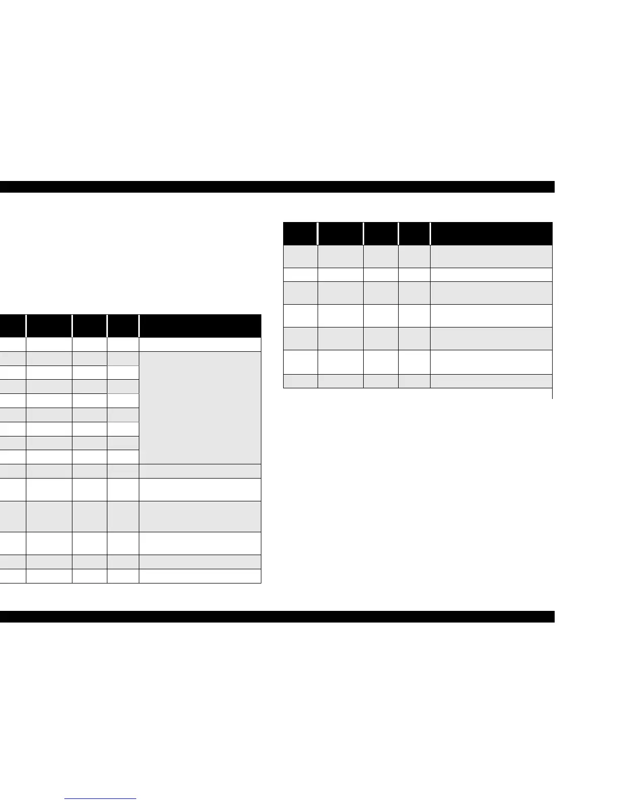
Table 1-7. Connector Pin Assignment and Signals
Pin No.
Signal
Name
Return
GND Pin
In/Out Functional Description
1 HostClk 19 In Host clock signal.
2 DATA0 20 In
The DATA0 through DATA7 signals
represent data bits 0 to 7,
respectively.
Each signal is at high level when data
is logical 1 and low level when data is
logical 0.
These signals are used to transfer
the 1284 extensibility request values
to the printer.
3 DATA1 21 In
4 DATA2 22 In
5 DATA3 23 In
6 DATA4 24 In
7 DATA5 25 In
8 DATA6 26 In
9 DATA7 27 In
10 PtrClk 28 Out Printer clock signal.
11
PtrBusy /
DataBit-3,7
29 Out
Printer busy signal and reverse
channel transfer data bit 3 or 7.
12
AckDataReq
/ DataBit-2,6
28 Out
Acknowledge data request signal
and reverse channel transfer data bit
2 or 6.
13
Xflag /
DataBit-1,5
28 Out
X-flag signal and reverse channel
transfer data bit 1 or 5.
14 HostBusy 30 In Host busy signal.
31 -INIT 30 In Not used.
32
-DataAvail /
DataBit-0,4
29 Out
Data available signal and reverse
channel transfer data bit 0 or 4.
36 1284-Active 30 In 1284 active signal.
18 Logic-H - Out
Pulled up to +5V via 3.9K ohm
resistor.
35 +5V - Out
Pulled up to +5V via 3.3K ohm
resistor.
17
Chassis
GND
- - Chassis GND
16,33,
19-30
GND - - Signal GND
15,34 NC - - Not connected
Note) In/Out refers to the direction of signal flow from the printer’s point of view.
Table 1-7. Connector Pin Assignment and Signals (continued)
Pin No.
Signal
Name
Return
GND Pin
In/Out Functional Description

 Loading...


