EPSON Stylus COLOR 860/1160 Revision C
Operating Principles Electrical Circuit Operating Principles 47
2.2.2.3 CR Motor Driver Circuit
The Stylus COLOR 860/1160 is equipped with a DC motor for the CR motor. In
addition to the CPU and ASIC, a slave CPU is mounted on the C298MAIN
board. Since the slave CPU is exclusively used to control DC motors, it
reduces duty of CPU and ASIC to offer faster data processing.
o CR motor driver circuit
The internal equivalent circuit of the CR motor driver IC (LB1947) is as
shown below.
Figure 2-19. Internal Equivalent Circuit of the CR Motor Driver IC
The
IC15 slave CPU
controls the CR position by referring to the pulses sent
from the linear encoder via IC8 ASIC. The CPU also sets an appropriate
drive current value for the CR position and the direction in which the CR
moves based on the data transmitted from the ASIC. So the slave CPU
outputs specified control signals to the motor driver. The motor driver IC18
then outputs the CR motor drive current to the CR motor based on the
signals sent from the
IC15 slave CPU
.
Unlike a stepping motor, the DC motor that drives the carriage
can not detect
the current carriage position by referring to the pulses given. For this
reason, a linear scale is attached along the carriage operation range to
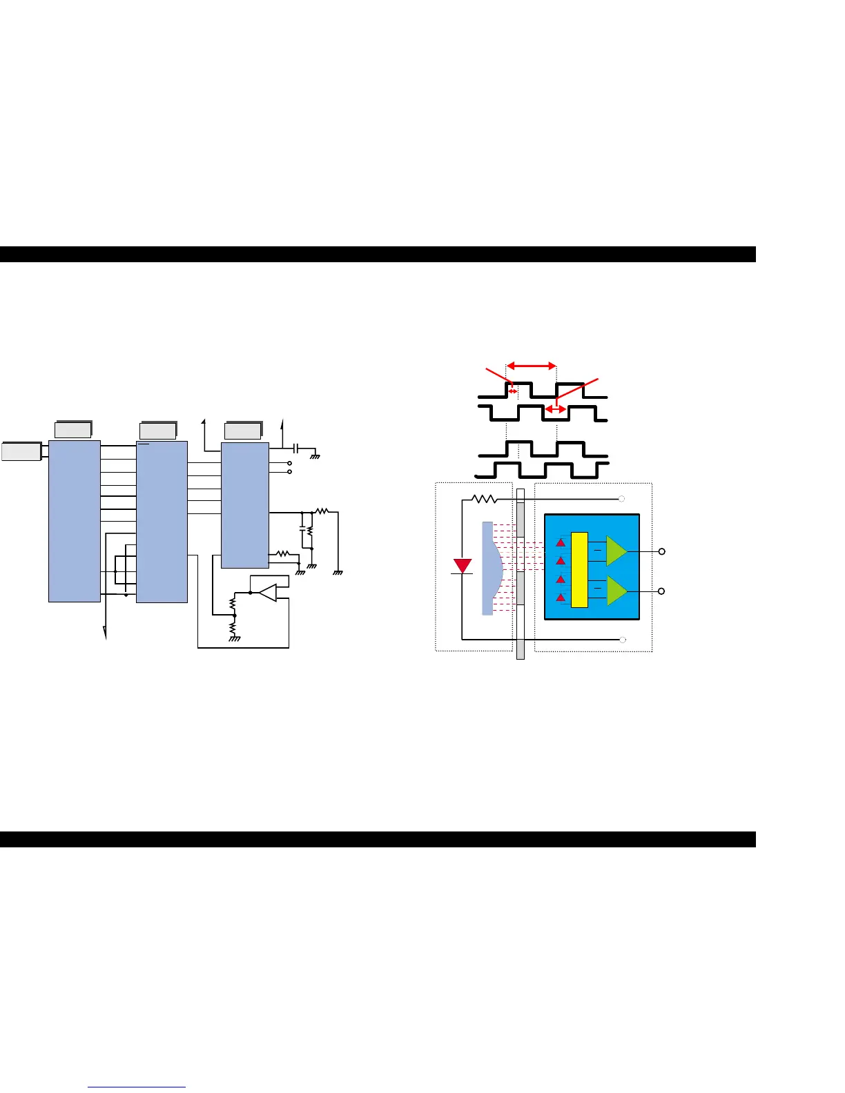
detect the carriage position. The linear encoder sensor outputs two
kinds of TTL level pulses Phase A and Phase B to IC8 ASIC.
Figure 2-20. CR Linear Scale Encoder Pulse
Direction for the current CR’s movement is detected based on the waveforms
of the Phase A and Phase B that are out of phase, while carriage position is
controlled by using the waveforms output from Phase A on a cycle basis (1
cycle: 1/180 inches). Phase between the output waveforms A and B is as
shown in Figure 2-20. Note all edges in Phase A, Phase B output waveforms
(1/720-inch cycle) are used to control the CR position while it is in the home
position for ink system.
IC 1 8
LB1947
IC 1 5
C 90A 13C A
IC 8
E05B 70C D
CR-A
CR-B
OUTA
OUTB
-
NMI
NMI
P31
RXD1
P33
TXD 1
P32
CRBI3
P30
CRPHAB
P64
CRENBB
RES
CRAI2
MD2
P25
CPU
CRBI3
CRAI0
ENA
ENB
CRAI1
CR
E
GND
R 115
68BK
R114
12.7K
C 117
1500p
R112
0.499
C 115
0.1U
+5V
+42V
VBB
IN 1
IN 2
ST
VI
MD
PE1
PE2
PE0
PE4
PA0
VREF
+
-
IC 2 4
M 62552FP
R138
4.4BK
R139
4.99BK
DA1
P12
P26
P11
P13
P27
CRBI2
CN8
Head FFC
A
A
B
B
+
-
+
-
Photo
D iodes
C om parators
LEN S
LED
Phase A
Phase B
Phase A
Phase B
Phase A
Phase B
1/720 inches
1/180 inches
1/360 inches
CR Motor CW rotation
CR motor CCW

 Loading...


