EPSON Stylus COLOR 860/1160 Revision C
Disassembly and Assembly Disassembly Procedures 82
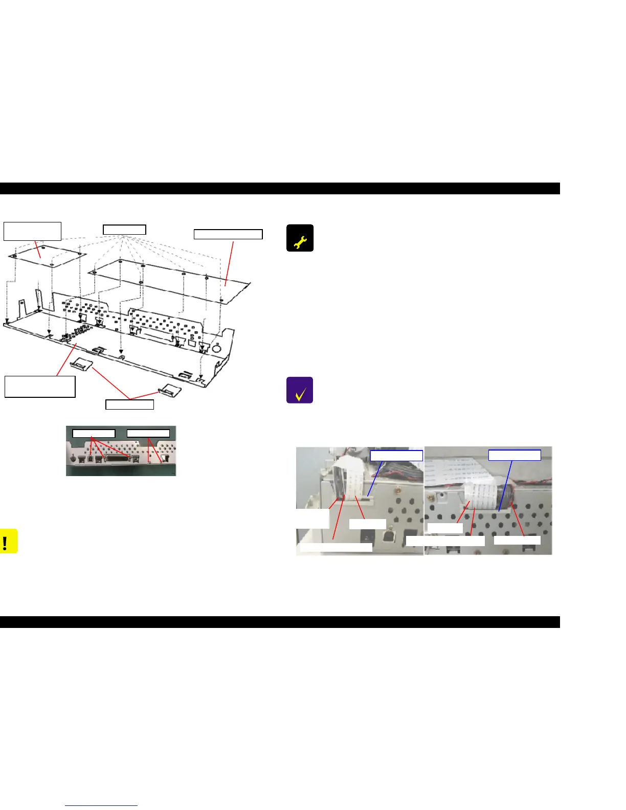
Figure 4-4. Removing Each Circuit Board
Figure 4-5. Setting the Cables to Holders A and B
CAUTION
n Since the CN10 is a locking connector, be sure to release
the locks before removing the cables.
Also, make sure to lock them when connecting the cable.
C298PSB/PSE
Board
C298MAIN Board
Shield Plate M/B
Assembly
Earth Plate
No1. Screws
No5. Screws
No1. Screws
ADJUSTM ENT
REQUIRED
Be sure to perform the following adjustments after replacing
the Main Board;
1. Head voltage ID Input (Refer to Chapter 5.)
2. Bi-D adjustment, including Head Gap Adjustment (Refer
to Chapter 5.)
3. USB ID data input (Refer to Chapter 5.)
Be sure to exchange the following parts also when replacing
the Main Board;
1. Waste Ink Absorption Pad
2. Ink Cartridge (BK & Color)
This parts exchange is required since the several ink
counters stored in the EEPROM are lost when the Main Board
is replaced.
CHECK
POINT
Make sure each cable is set in the correct cable holder (A or
B) on the M/B Shield Plate. Refer to Figure 4-5.
Cable Holder B
ASF HP Sensor Cable
CR, PF Motors
PE Detector
Cable
Head FFC
CR Encoder Sensor FFC
Panel FFC
Cable Holder A

 Loading...


