EPSON Stylus COLOR 860/1160 Revision C
Disassembly and Assembly Disassembly Procedures 98
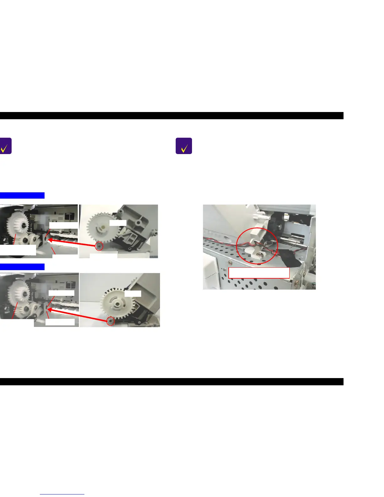
Figure 4-31. Assembling notice for ASF Assembly.
Figure 4-32. Setting the ASF HP Sensor & PF Motor cable
CHECK
POINT
n When installing the ASF assembly, make sure that the
protrusion on the ASF is assembled into the fixing hole in
the Middle Frame.
n Engage the Gear 32 (ASF Unit) and Combination Gear 14,28
(DE unit) carefully when installing the ASF unit is to the
Bottom Frame. Otherwise, gears may be damaged. Refer to
Figure 4-31.
Stylus COLOR 860
Protrusion on
the ASF
Combination Gear
14, 28
Gear 32
Middle Frame
Fixing Hole
Middle Frame
Protrusion on
the ASF
Gear 32
Combination Gear
14, 28
Stylus COLOR 1160
Fixing Hole
CHECK
POINT
n Screws for ASF Assembly should be used at the following
positions. (Looking from the back of printer). Refer to
Figure 4-29.
- Right Side (viewed from the back): ASF Fixing Screw
- Left side (viewed from the back): Screw No.7
n Make sure the ASF HP sensor cable and the PF Motor
Cable are set in the hook on the right side (viewed from
the back) of ASF unit. Refer to Figure 4-32.
Setting the ASF HP Sensor and
PF Motor Cable to the hook.

 Loading...


