EPSON Stylus CX3500/CX3600/CX3650/CX4500/CX4600 Revision A
DISASSEMBLY AND ASSEMBLY Disassembly 138
4.3.11.2 Stylus CX4500/CX4600
V External View (1)
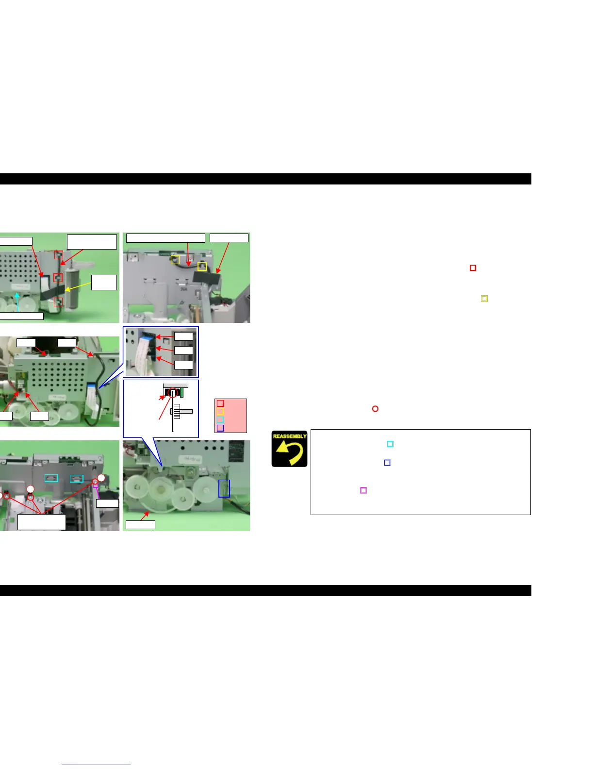
Figure 4-26. Main Board Unit Removal (1)
V Part/Unit that should be removed before removing Main Board Unit.
Document Cover / Paper Support Assy. / Scanner Unit / Panel Unit /
Housing Upper / Printer Mechanism
V Removal procedure
1. Peel off the acetate tape (x1) for securing Head FFCs (x3)
2. Release PG Sensor Connector Cable from the hooks (x3, ) of Main Board
Unit.
3. Peel off the acetate tape (x1) for securing PE Sensor Connector Cable, and
then release PE Sensor Connector Cable from the hooks (x2, ) of Main
Board Unit.
4. Disconnect the following cable connectors and FFC from the connectors of
Main Board.
• CN3: PE Sensor Connector Cable
• CN4: PG Sensor Connector Cable
• CN5: Head FFC
• CN6: Head FFC
• CN7: Head FFC
• CN8: PF Motor Connector Cable
• CN9: CR Motor Connector Cable
5. Remove the screws (x3, ) for securing Main Board Unit, and then remove
Main Board Unit from Printer Mechanism.
PG Sensor
Connector Cable
Main Board Unit
Head FFC
Acetate
tape
Acetate tape
PE Sensor Connector Cable
CN4CN3
CN8CN9
C.B.S 3x6 F/Zn
(7±1kgfcm)
1
2
3
Dowel
CN7
CN5
CN6
PF Scale
Slit
PF Encoder
Sensor
Hooks
Ribs
Rib
Hooks
T Insert PF Scale into the slit of PF Encoder Sensor.
T Insert the ribs (x2, ) of Main Frame into the hooks (x2) of
Main Board Unit.
T Insert the rib (x1, ) of Main Board Unit into the hook (x1) of
Main Frame.
T Align the positioning hole (x1) of Main Board Unit with the
dowel (x1, ) of Main Frame.
T Tighten the screws of Main Board Unit in order shown by
figure.

 Loading...


