EPSON Stylus Photo R1900/R2880/R2000/R2000s/SC-P400 Series Revision I
Disassembly And Assembly Disassembling the Printer Mechanism 97
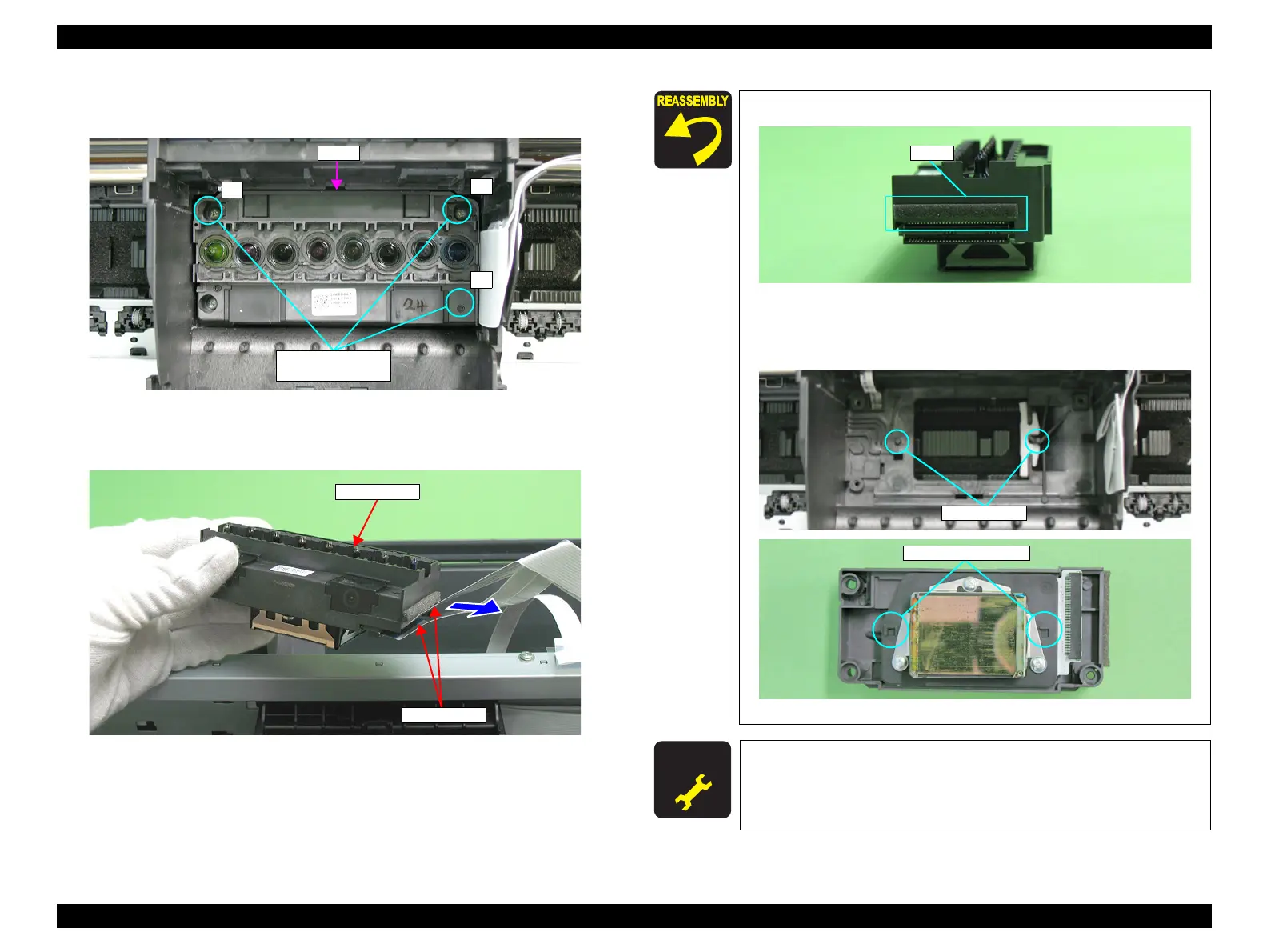
11. Remove the three C.B.P. M2.6 x 8 that secure the Printhead using the Phillips
Screw Driver, No.1, and vertically lift the Printhead to remove it.
Figure 4-57. Removing the Printhead
12. Remove the two Head FFCs from the Printhead.
Figure 4-58. Remove the Head FFC
7) C.B.P. M2.6x8
(3±0.5 kgf.cm)
1
2
3
Head
Confirm that the pad is attached at the position in Figure 4-59.
Figure 4-59. Attaching the Pad
The Printhead must be installed with its positioning holes
aligned with the guide pins of the Carriage Unit.
Figure 4-60. Reinstalling the Printhead (1)
A D J U S T M E N T
R E Q U I R E D
After replacing or removing the Printhead, always make the required
adjustments referring to the following.
•“Chapter 5 Adjustment (p.139)”

 Loading...


