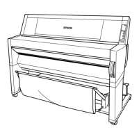
Epson Stylus Pro 7700/7710/7700M/7710M/7900/7910/9700/9710/9900/9910/WT7900/WT7910/9890/9908/7890/7908 Revision I
DISASSEMBLY & ASSEMBLY Disassembly and Assembly Procedure 295
Confidential
6. Remove the AID Board.
7. Disconnect the connector (CN2), and the FFC (CN1) on the AID Board.
Figure 4-148.
Removing the
AID Board
After installing the AID Board Cover, check the status of the cable
connected to the CN2 on the AID Board, and if the black and white
cables can be seen, place the white one over the black one.
<Black and white cables are hidden>
No treatment required
<Black & white cables can be seen>
Place the white over the black
CN2
CN1
AID Board
- Top right -
C H E C K
P O I N T
When installing the AID Board before design change, it can be
reassembled by reversing the disassembly procedure in
“Disassembling procedure for the previous type before
design change” (p294)
.
When installing the new-shaped AID Board to the old main
body, follow the procedure below.
1. Remove the Spindle Cover R.
(p215)
2. Remove the two screws that secure the AID Board mounting
plate, and remove the AID Board mounting plate.
3. Secure the new AID Board and AID Board mounting plate with
the two screws.
4. Fold the FFC as shown below and connect the connector and
the FFC to the AID Board.
- Top right -
CN2
CN1
- Top right -
Folded part of FFC
AID Board + AID Board mounting plate
 Loading...


