T3-B T6-B Maintenance 8. Cable
48 T-B series Maintenance Manual Rev.1
Turn ON the Manipulator and change the motor to OFF status (MOTOR OFF).
Press and hold the brake release switch to let the shaft down. Be sure to keep enough
space and prevent the end effector hitting any peripheral equipment.
The brake release switch affects only Joint #3. When the brake release switch is pressed,
the Joint #3 brake is released.
Be careful of the shaft falling while the brake release switch is being pressed because
the shaft may be lowered by the weight of the
end effector.
Manipulator.
Remove the power unit cover.
Reference: 7.5 Power Unit Cover
Remove the ground wire that secured on the case side cable fixing plate.
Cut off the wire tie binding the cables in the Base
side.
plate.
Reference: 7.4 Connector Plate
Remove the following parts that connected to the connector plate (inside).
Air tube
TP connector
-B : Remove the base side cover.
Reference: 7.6 Base Side Cover
-B : Remove the connector of regenerative resistor
junction cable.
Unscrew the mounting bolts of the joint #1 AMP
board plate and the regenerative resistor plate.
Mounting bolts: 4-M4×8 Sems
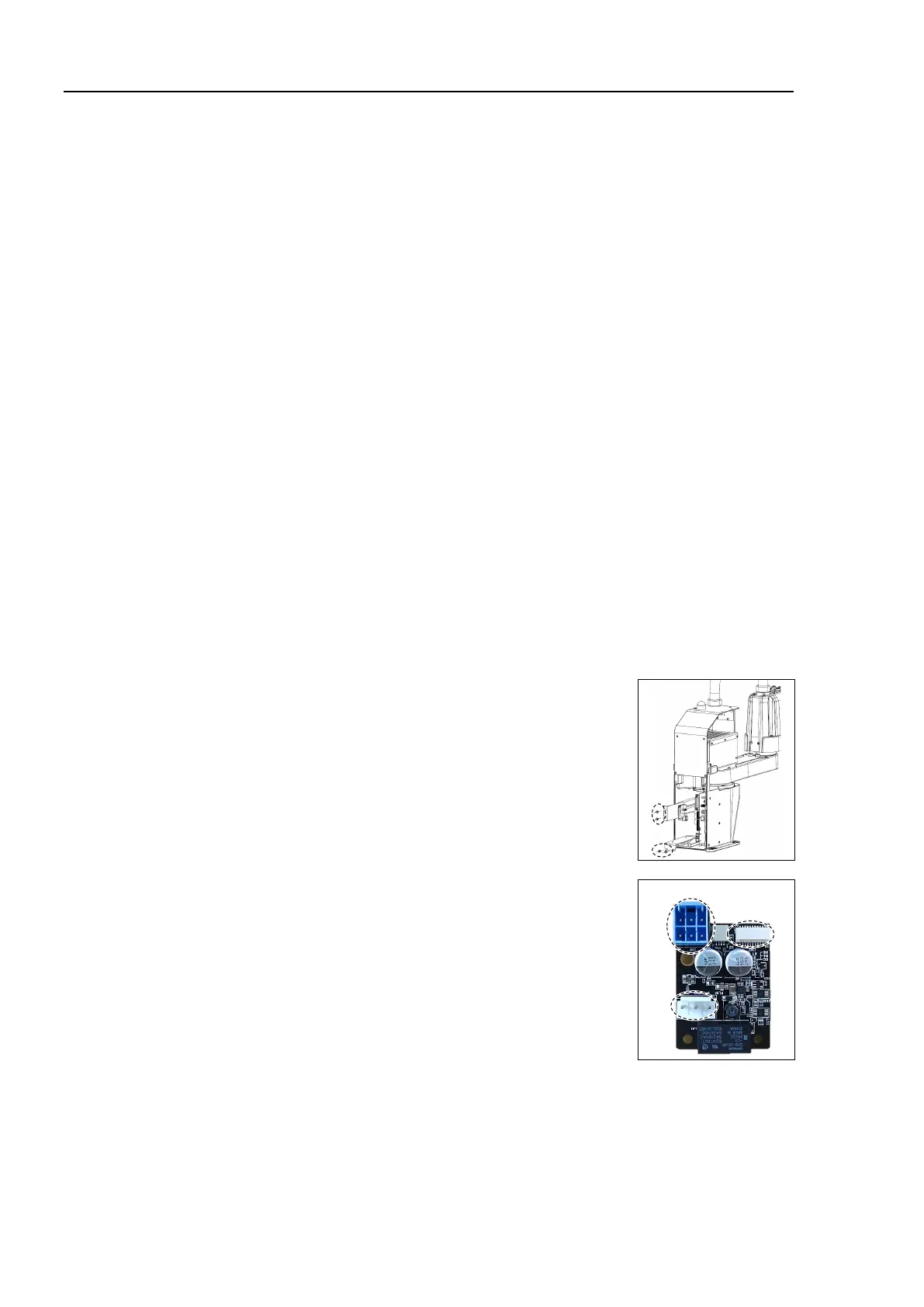
connector of AMP board.
A: Power cable connector
B: Signal cable connector
C: Motor connector

 Loading...


