T3-B T6-B Maintenance 8. Cable
T-B series Maintenance Manual Rev.1 49
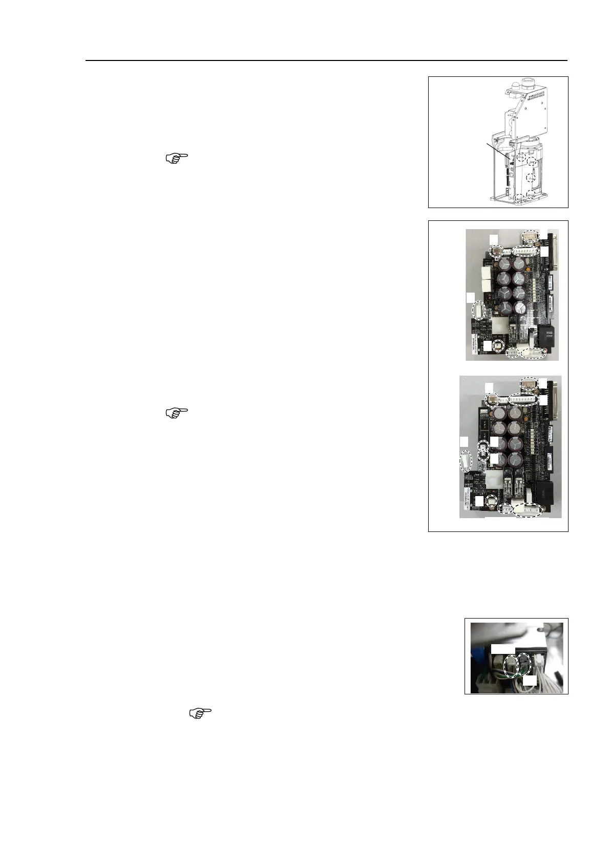
Unscrew CPU/DPB board mounting screws.
Hexagon socket head cap button bolt: 5-M3×5
board from a base.
Radiation sheet is attached on the back of CPU/DPB
board. Be careful not to lose or break it.
CPU/DPB board connector.
A: Power connector (IN/OUT ×1 for each)
B: Power cable connector (×1)
C: Signal cable connector
D: Hand I/O connector
E: LED connector
F: Regenerative resistor 1 (T6-B only)
G: Regenerative resistor 2 (T6-B only)
H: Battery connector
Remember the cable layout for reconnecting the
cables
correctly after replacement.
Remove the arm top cover.
Reference: 7.1 Arm Top Cover
Reference: 7.7 User Plate
Remove the connector of the
Joint # 2, 3, 4 motor unit and
the connector of the AMP board.
Motor Unit
Signal cable connector (IN/OUT ×1 for each)
Signal cable for joint #4 is IN only.

 Loading...


