T3-B T6-B Maintenance 9. Joint #1
T-B series Maintenance Manual Rev.1 65
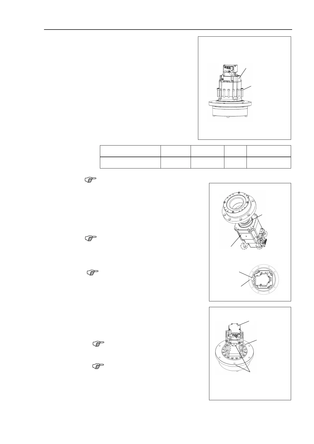
units mounting
Rotate the motor around the shaft so that
the reduction gear units mounting screws
are visible, then operate.
T6-B: 16-M4×22
Loosely fasten all bolts in a crisscross
pattern so that the bolts will be fastened
evenly.
torque wrench, tighten each
bolt securely in a crisscross pattern at the
torque specified in the table below.
Name Model Bolt type Bolts Tightening torque
Joint #1 reduction gear units T6-B M4×25 16 5.5 ± 0.25 N⋅m
Be careful not to apply too much force since it may damage the parts.
T3-B : Set the O-ring (between the motor and
the flange) on the motor mounting
surface, and temporarily secure the
motor unit on the Joint #1 flange.
4-M4×15+small washer
Be careful of the direction of the motor. Align
the orientation of the motor board with the
alignment dent in the flange.
Secure temporarily the screws.
After this, an alignment of the reduction gear
units are performed.
(Secure so that the screw head lightly touches
the flange base.)
-B: Mount the motor mounting screws.
4-M4×12+small washer
Be careful of the direction of the motor.
Align the orientation of the motor board
with the alignment dent in the flange.
Secure temporarily the screws.
After this, an alignment of the reduction
gear units are performed.
(Secure so that the s
touches the flange base.)
Align the orientation
of the motor board
with the dent

 Loading...


