T3-B T6-B Maintenance 9. Joint #1
68 T-B series Maintenance Manual Rev.1
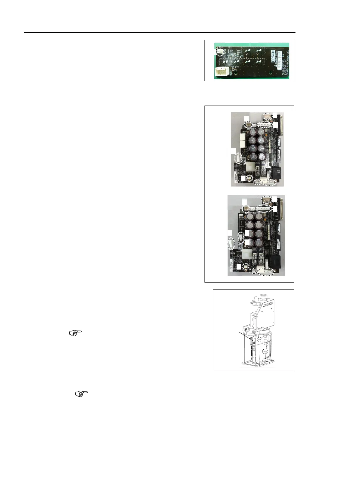
Connect the LED board connector.
A: LED - LED board connector
Connect the connector of Joint #1 motor unit.
Signal cable connector (IN/OUT ×1 for each)
Connect CPU/DPB board connector.
A: Power connector (IN/OUT ×1 for each)
B: Power cable connector (×1)
C: Signal cable connector
D: Hand I/O connector
E: LED connector
F: Regenerative resistor 1 (T6-B only)
G: Regenerative resistor 2 (T6-B only)
H: Battery connector
Mount CPU/DPB board to base.
Hexagon socket head cap button bolt: 5-M3×5
Tightening torque: 0.45 ± 0.1 N·m
Attach the radiation sheet on the back side of the
CPU/DPB boards when mounting.
Attach the radiation sheet on the back side of the AMP board.

 Loading...


