T3-B T6-B Maintenance 9. Joint #1
T-B series Maintenance Manual Rev.1 69
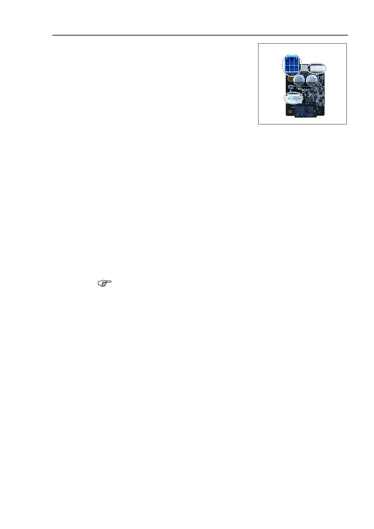
Connect the AMP board connector.
A: Power cable connector
B: Signal cable connector
C: Motor connector
-B: Mount the base side cover.
Reference: 7.6 Base Side Cover
-B: Mount the Joint #1 AMP board plate.
Connect the following parts to the inside of the connector plate.
Air tube
TP connector
Mount the Power unit cover.
Reference: 7.5 Power Unit Cover
Mount the connector plate.
Reference: 7.4 Connector Plate
Reference: T-B series Manual T3-B T6-B Manipulator 6.5 LED
DO NOT turn OFF the power until the Manipulator starts.
When you connect a motor unit connected to another axis, an error 5009 or 9709
will occur. To clear the error,
enter the following command in [Command Window]
and execute it.
Joint #1: > MUIDReset 1
Joint #2: > MUIDReset 2
Joint #3: > MUIDReset 3
Joint #4: > MUIDReset 4
Reboot the Controller.
Perform the calibration for the Joint #1.
Reference: 17. Calibration

 Loading...


