47
Chapter 2 Setup
2
4
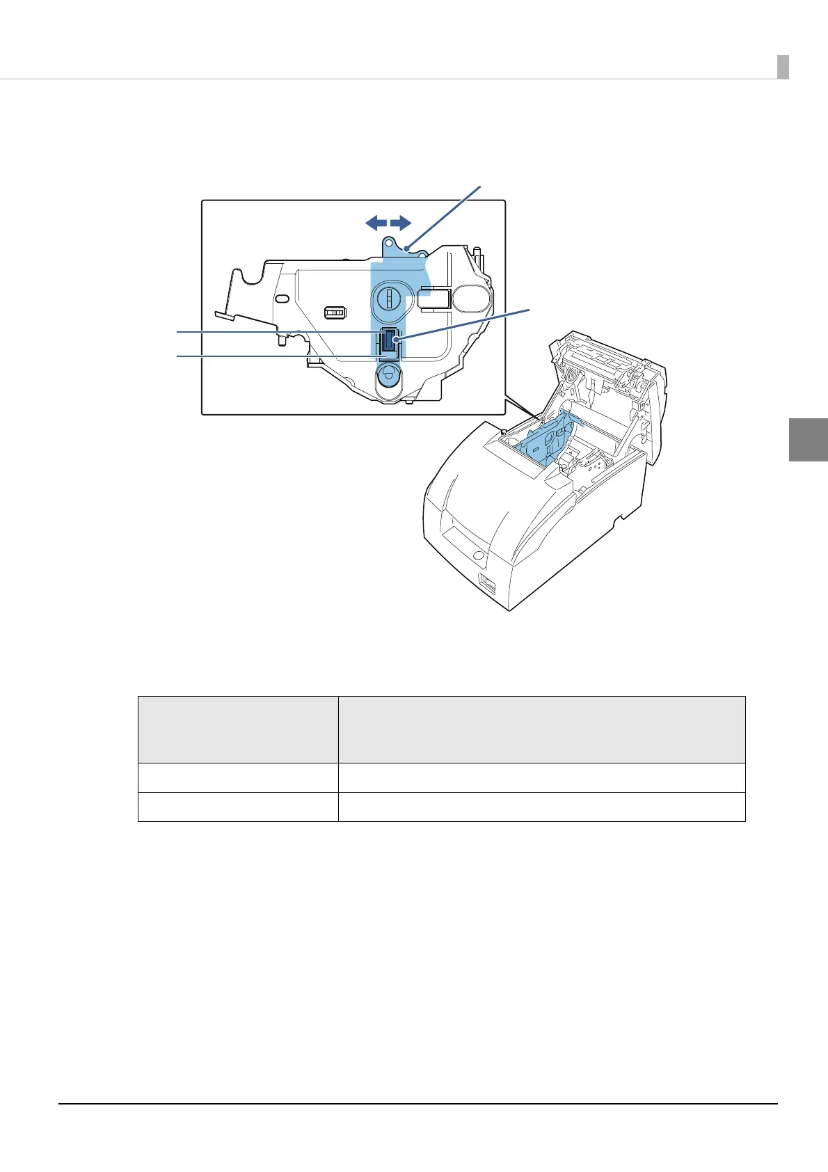
Adjust the detector by sliding the lever in the direction shown below.
The table below shows the point at which the near-end detector i s triggered. Note that this
figure is a calculated value, and there may be some variations, depending on the printer.
Detector position
(attaching point of the
detector adjustment lever )
Trigger point (included the thickness of paper roll core)
#1 setting Approx. 8 mm {0.315"}
#2 setting Approx. 5 mm {0.197"}
Knob
Detector lever
#1 setting
#2 setting

 Loading...


