10
630791 DS MKII INSTALLATION MANUAL
B CREATING THE CAVITY
B1 Cavity Shape
The DS Series re is suitable for self supporng mber or steel framed cavies. Most exisng masonry cavies
will not be suitable.
B2 Designing the Cavity
The following aspects must be considered when designing this installaon:
ͳ Appliance physical size
ͳ Wall nishing and interacon with appliance
ͳ Posioning of appliance with regard to wall lining (depth into wall)
ͳ Exhaust terminaon aspect – horizontal/vercal and ue conguraon
ͳ Flue exhaust fan noise
ͳ Exhaust cowl access for maintenance
ͳ Gas pipe layout
ͳ Gas isolaon valve / pressure test point posion
ͳ Electrical isolaon switch
ͳ Home automaon network connecons
THIS DS SERIES FIRE IS TO BE INSTALLED PRIOR TO ANY WALL LINING.
THE WALL LINING IS THE VERY LAST TASK TO BE COMPLETED IN THIS INSTALLATION.
The cavity and wall linings may be constructed from standard mber framing materials and do not need to be
non-combusble.
It is not necessary to line the sides or back of the cavity.
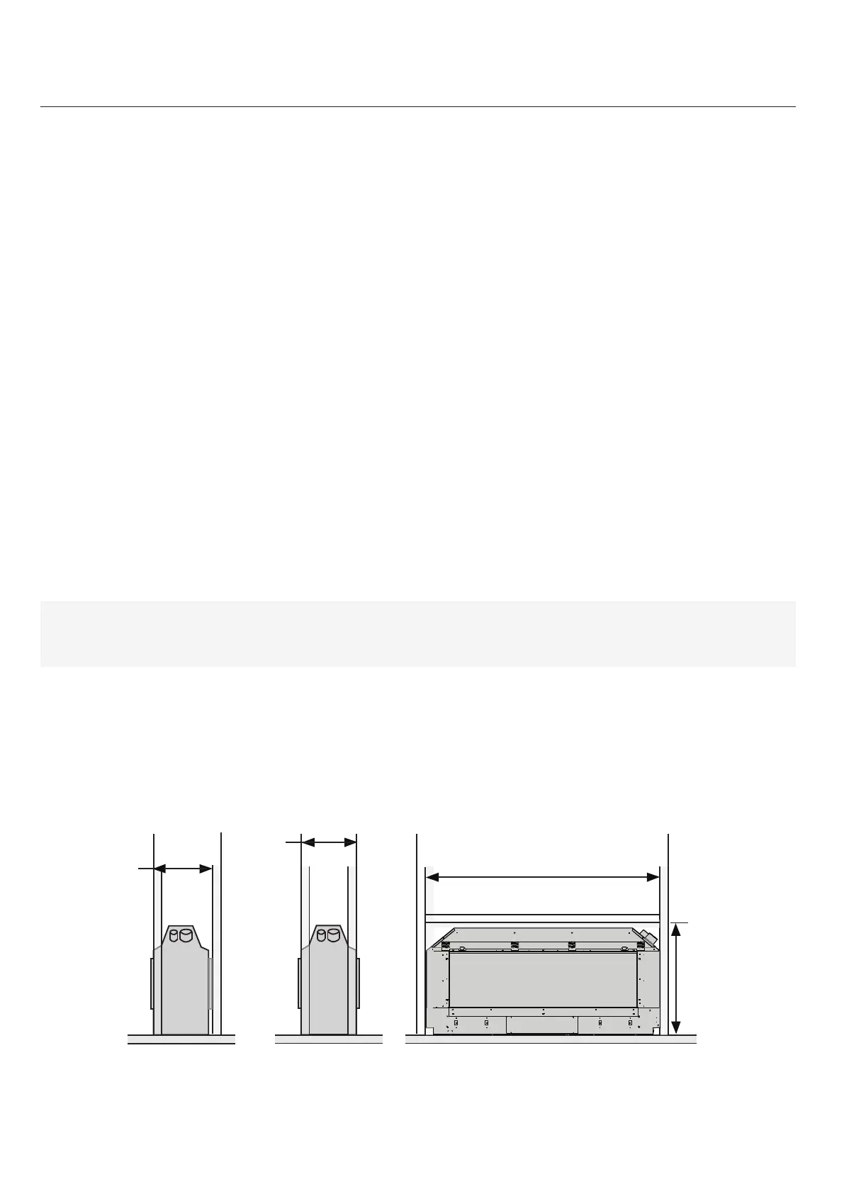
Note: Dimensions shown do not include all allowances for clearances to combusbles to the ue.
B
min*
D min*
Side
Single Sided
Side
Double Sided
Front
A
min*
C
min*
*Dimensions shown do not include allowances for
clearance to combustibles to the flue