C
17
630791 DS MKII INSTALLATION MANUAL
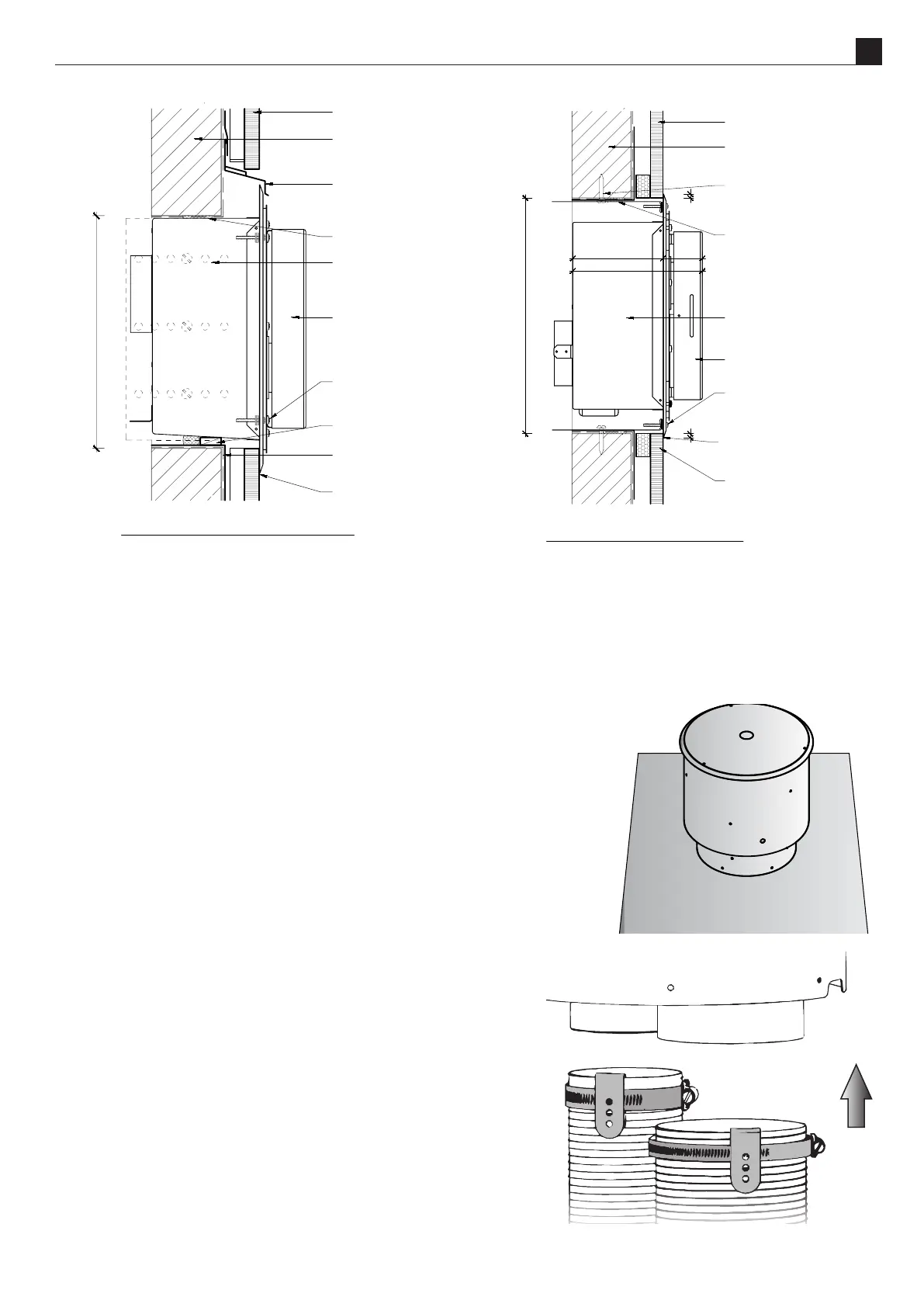
Head and Sill scale 1:5
framing member with
wall wrap and flashing
tape over
cladding on cavity
batten
typical head flashing with
stop ends to comply with
relevant building code
horizontal powerflue
unit
terminal fixing brackets
(shown dashed) fixed
to framing
flashing tape over wall
wrap to opening
seal air gap to opening
terminal screw fixed to flange
with flange fixed to studs at
fixing brackets
packer to lift terminal off
sill
sill cover to cladding to comply
with relevant building code
300 min
360 min
10
cladding on cavity
batten
10
horizontal powerflue
unit
terminal screw fixed to flange
with flange fixed to studs at
fixing brackets
terminal fixing
brackets screw fixed
into framing
framing member with
wall wrap and flashing
tape over
continuous sealant strip
to jambs
scriber or plug may be
required - dependent on
cladding type
seal air gap to opening
cowl
198
138 60
scale: date:
ecn:
drawn:
drawing no:
revision:file:
Horizontal Powerflue Detail
as shown ECN-2155 EDA-0006 MGD-Series FLUE Master File.dwg
V. 02 08.12.2017
Jamb scale 1:5
framing member with
wall wrap and flashing
tape over
cladding on cavity
batten
typical head flashing with
stop ends to comply with
relevant building code
horizontal powerflue
unit
terminal fixing brackets
(shown dashed) fixed
to framing
flashing tape over wall
wrap to opening
seal air gap to opening
terminal screw fixed to flange
with flange fixed to studs at
fixing brackets
packer to lift terminal off
sill
sill cover to cladding to compl
with relevant building code
300 min
360 min
10
cladding on cavity
batten
10
horizontal powerflue
unit
terminal screw fixed to flange
with flange fixed to studs at
fixing brackets
terminal fixing
brackets screw fixed
into framing
framing member with
wall wrap and flashing
tape over
continuous sealant strip
to jambs
scriber or plug may be
required - dependent on
cladding type
seal air gap to opening
cowl
198
138 60
scale: date:
ecn:
drawn:
drawing no:
revision:file:
Horizontal Powerflue Detail
as shown ECN-2155 EDA-0006 MGD-Series FLUE Master File.dwg
V. 02 08.12.2017
C4
The UVP is designed to have the enclosure containing the fan unit mounted externally. Escea recommends this
install for a UVP powerue; an example is shown below.
Ensure the 43mm restricon plate is installed on the inlet.
The cowl surround should be xed in place as shown right.
Mount the UVP kit to the top of a chimney ashing plate or penetrate the
roof with an oponal ue liner accessory and t the UVP kit over the ue
liner, sealing the penetraon with a deckte or similar ashing.
Ensure the terminal is vercal and rigidly mounted and the exi ue
aached below is xed to the terminal spigots using the supplied hose
clamps and aid clips.
Place the clamp over the exi ue and the clip over this. Make sure
the exi tube has been stretched out as far as possible where the
hose band clamps are going to be aached (not sll compressed).
Slide the exi tube over the spigot and hold it in place by drilling
one hole through the spigot using the clip guide hole and riveng
the three components together.
NOTE: If this install is impraccal for your situaon see
informaon regarding an internal install of the UVP, go to
secon C5 on page 18.