C
14
630791 DS MKII INSTALLATION MANUAL
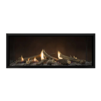
0.4m Min.
8m Max.
Overall ue length:
Vercally Terminated: Ulises the Escea Universal Vercal Power Flue enclosure kit.
Y
X
X + Y = 8m MAX
= 0.4m MIN*
* Excess noise may be present at this distance
8m MAX
1.2m F-F Liner
UVP Cowl
Liner
UVP Unit
8m MAX
External
Y
X
X + Y = 8m MAX
= 0.4m MIN*
* Excess noise may be present at this distance
8m MAX
1.2m F-F Liner
UVP Cowl
Internal
C2
If your ue system is greater than 8m long (up to 40m long), then please contact the Escea Advisory Team at
aa@escea.com for further guidelines.
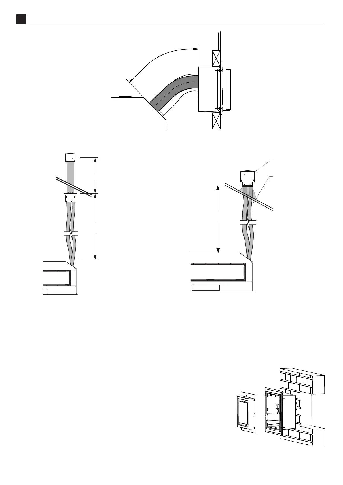
C3
NOTE: The appliance is designed only to operate using the approved exible
or PolyPro ue supplied by Escea. Other brands of ue may not t, and this
will aect the appliance warranty.
The Horizontal Power Flue Wall Terminal must be installed in the correct
orientaon (the small horizontal slot should be at the boom). This allows for
the correct operaon of the ue system and prevents the ingress of water.
The horizontal powerue wall terminal must be weather ght when installaon
is complete to prevent damage to the dwelling. It must be installed by a suitably
qualied person.