EasyManua.ls Logo

Excillum MetalJet D2+ User Manual

Excillum MetalJet D2+
103 pages
To Next Page IconTo Next Page
Page #1 background imageLoading...
Page #1 background image
Revision 19, November 2016
MetalJet D2+ Operating manual

Table of Contents

Questions and Answers:

Excillum MetalJet D2+ Specifications

General IconGeneral
BrandExcillum
ModelMetalJet D2+
CategoryLaboratory Equipment
LanguageEnglish

Summary

1 INTRODUCTION

1.3 Product Information

Details about the MetalJet D2+ source, including identification and components.

1.3.1 Product Identification

Information required for product identification with Excillum, including model and serial numbers.

1.3.2 Design and Function

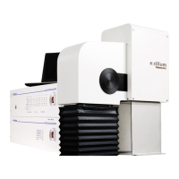
Overview of the MetalJet D2+ system's operation, including its metal-jet anode and electron gun.

2 SAFETY

2.1 Safety Precautions

General safety measures including qualified personnel, partly completed machinery, and manual.

2.1.1 Qualified Personnel

Specifies requirements for personnel involved in installation, commissioning, and operation.

2.1.4 X-ray Radiation

Details hazards of X-ray radiation and precautions, including personal monitoring and protective devices.

2.1.5 Electricity and High Voltage

Covers safety precautions for electrical work, high voltage, and grounding techniques.

2.1.6 High Pressure

Warns about high liquid-metal pressure in the jet system and required personnel for maintenance.

2.1.9 Poisoning Hazard

Warns about the toxicity of beryllium foil in the exit window and handling procedures for breakage.

3 TRANSPORT AND STORAGE

3.1 Transport

Guidelines for transporting the MetalJet D2+ source, including upright position and handling of dangerous goods.

4 INSTALLATION

4.1 Initial Installation Checklist

A checklist for pre-installation and during installation steps to minimize complications.

4.3 Setting up the MetalJet D2+ Source

Instructions for setting up the MetalJet D2+ source after unpacking.

4.3.1 Mounting of Sub-assembly Units

Details on connecting and mounting the electron gun/x-ray head and pump box semi-rigidly.

4.3.2 Connecting Tubing and Cables

Step-by-step guide for connecting various tubing and cables for system assembly.

4.3.2.2 Flex-hose Assembly and Jet-Exit Port

Procedure for connecting the flex-hose assembly to the jet-exit port and attaching the cooling block.

4.3.2.3 Cooling Water Supply and Return

Describes routing and connecting cooling water supply and return hoses to subassemblies.

4.3.2.4 High-Pressure Tubing and Nozzle Assembly

Instructions for connecting the high-pressure tubing to the nozzle assembly using a VCR gasket.

4.3.2.6 Cooling Water

Guidelines for installing and verifying the water cooling solution for system operation.

4.3.2.7 Interconnecting Cables

Instructions for connecting interconnecting cables between system components based on cable part numbers.

4.3.2.10 Mains Supply

Instructions for connecting grounding cables and mains supply to system modules.

4.4 Safety System

Explains the implementation of a customer-supplied safety system interface for the source.

4.4.1 High Voltage Controller

Details the role of the high voltage controller in the safety system, including relays and monitor outputs.

4.6.2 Network Connectivity

Guidelines for connecting the system controller to a local network and remote access.

5 OPERATION

5.2 Starting the MetalJet D2+ System

Flowchart illustrating the decision process for starting the MetalJet D2+ system.

5.4 Starting the Software and GUI

Step-by-step guide for starting the XCS software and accessing the Graphical User Interface (GUI).

5.8 Parametrization

Procedure for system parametrization, consisting of six steps for setting up cathode and electron optics.

5.8.1 Prepare System for Parametrization

First step in parametrization: setting system to Admin level, desired acceleration voltage, and Lowpower state.

5.8.2 Align Electron Beam to Optical Axis

Aligns electron beam by adjusting alignment coils and focus lens, and centers the electron-beam dump aperture.

5.8.3 Determine Jet Size and Position

Determines liquid-metal jet size and position by sweeping the electron beam across it.

5.8.4 Characterize Focus Lens and Verify Jet Stability

Maps electron-beam spot sizes for different focus settings and verifies jet stability.

5.8.5 Characterize Linefocus Coils

Characterizes linefocus coils to establish correlation between coil settings and electron-beam spot geometry.

5.9 Set Emission Power and Spot Size

Adjusts focus lens for hysteresis and calibrates electron beam spot size and settings.

5.10 Normal Operation

Procedures for normal operation, including turning X-ray generation on/off and changing settings.

6 MAINTENANCE AND SERVICE

Summary of Systems and Components Requiring Maintenance

Table summarizing components requiring maintenance and service, with intervals and references.

6.1 Vacuum System

Details maintenance for roughing pump and turbopump, including troubleshooting and replacement recommendations.

6.2 Jet System

Maintenance procedures for the jet pump, including lubricants, diaphragm, and check valves.

6.2.4 Nozzle Assembly

Guidance on nozzle failure, recommendations for replacement, and troubleshooting for contamination.

6.3 Electron Gun

Maintenance and operation of the electron gun, focusing on the cathode assembly and beam dynamics.

7 SHUTDOWN

8 MALFUNCTION AND TROUBLESHOOTING

High Voltage Generator Shuts Down Repeatedly Due to Arcing

Possible causes and remedies for repeated shutdowns of the high voltage generator due to arcing.

No Electron-Beam Emission

Troubleshooting steps for when there is no electron-beam emission, often related to cathode assembly.

9 CUSTOMER SUPPORT

9.2 Remote Support

Details how to use TeamViewer for remote support and troubleshooting with Excillum.