METALJET D2+ INSTALLATION
Revision 19, November 2016 Page 4-15
4.3.2.7 Interconnecting cables
1. Connect all interconnecting cables between x-ray head, x-ray system controller, x-ray high-voltage
controller and pump box according to Table 4-1 below. Refer to Section 4.3.2.8 and Figure 4-15, Figure
4-16, and Figure 4-17 regarding connector locations for MetalJet D2+ 70 kV systems and Section
4.3.2.9 and Figure 4-15, Figure 4-21, and Figure 4-22 for MetalJet D2+ 160 kV systems.
Note: The cables connecting the x-ray head to the x-ray system controller and the x-ray high-voltage
controller has a standard length of 5 m, but they can also be supplied in a 10 m version.
E-009-0037 (5 m)
E-009-0236 (10 m)
DP (x-ray system controller)
E-009-0151 (5 m)
E-009-0234 (10 m)
B1 (x-ray system controller)
E-009-0153 (5 m)
E-009-0233 (10 m)
B2 (x-ray system controller)
E-009-0036 (5 m)
E-009-0238 (10 m)
U3 (x-ray system controller)
E-009-0079 (5 m)
E-009-0237 (10 m)
U5 (x-ray system controller)
E-009-0038 (5 m)
E-009-0235 (10 m)
SN (x-ray high-voltage controller)
D-HV (x-ray system controller)
D-HV (x-ray high-voltage controller)
A-HV (x-ray system controller)
A-HV (x-ray high-voltage controller)
A-PB (x-ray high-voltage controller)
D-PB (x-ray high-voltage controller)
Table 4-1. List of interconnecting cables to be connected during installation.
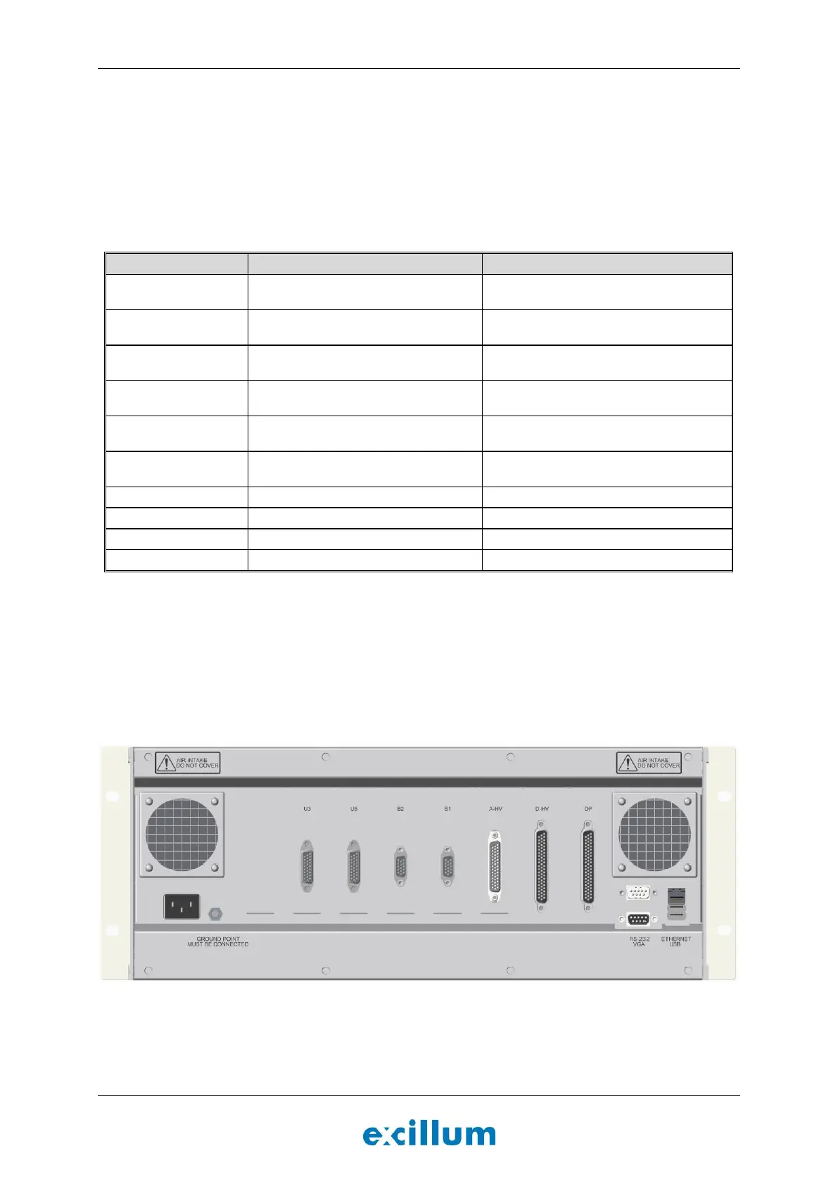
2. Connect the system to the local network using the Ethernet port in the back of the x-ray system
controller, see Figure 4-15.
Note: Monitor, keyboard and mouse can also be connected to the x-ray system controller. However,
normally the system is accessed over TCP/IP using the VNC server running on the x-ray system
controller.
Figure 4-15. X-ray system controller seen from behind.