METALJET D2+ OPERATION
Revision 19, November 2016 Page 5-10
This will ramp up the high voltage of the electron gun and the electron-beam power to the
“Lowpower” setting. The actual value is determined by the minimum spot size achievable for
the cathode installed and can be changed when the user level is set to “Service”.
4. Wait for the green button to indicate that the “Lowpower” state is reached and that the emission
current is stabilized at the low power setting.
5.8.2 Align electron beam to optical axis
The next step is to align the electron beam to the optical axis of the column. This is done automatically by the
“Align” step.
5. Click the Align button.
This initiates a routine that sweeps the current of the alignment coils at the same time as it
changes the focus lens current between two preset values.
The routine will repeat itself until it finds the alignment coil currents that result in the
smallest shift in electron-beam position between the two focus lens currents.
In addition, it aims at centering the electron-beam dump aperture.
6. Wait for the green button to indicate that the “Align” state is reached.
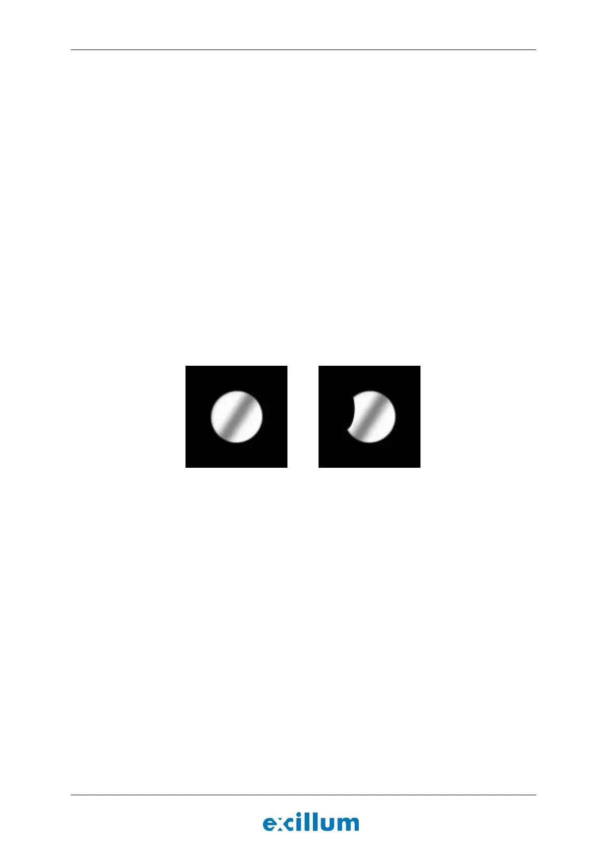
7. Go to the “Results” tab, select “Deflectorscan” under last images and inspect the image. If the system
is ok the image of the electron-dump should be a round circle free from metal debris, see Figure 5-6
(left image).
Figure 5-6. Deflectorscan of clean (left) and contaminated (right) electron-beam dump aperture.
8. If the alignment algorithm finishes without errors, proceed to Section 5.8.3. The Align button will turn
green if no errors occur.
9. If the mechanical alignment accuracy of the HV feedthrough is insufficient, this step may fail and the
HV feedthrough must be mechanically aligned. Refer to the service manual under Align HV
feedthrough for instructions.
NOTE: The spot size calibration accuracy is negatively affected, by deflection aberrations, if high
currents are required in the alignment coils. Aligning the HV feedthrough aim at minimizing the
amount of current that is required.
10. If the electron-beam dump aperture is contaminated, see Figure 5-6 (right image), the liquid-metal
debris must be removed before proceeding. Refer to the service manual under Remove liquid-metal
debris from electron-beam dump aperture for instructions.
5.8.3 Determine jet size and position
The next step is to determine the size and position of the liquid-metal jet.
8. Click the Segment button.
The electron beam will repeatedly sweep across the liquid-metal jet in order to
determine the rough position and geometry of the jet.