METALJET D2+ OPERATION
Revision 19, November 2016 Page 5-11
9. Wait for the green button to indicate that the “Segment” state is reached.
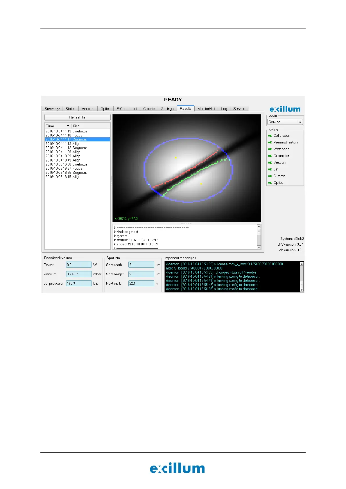
10. Go to the “Results” tab, select “Segment” in the images list and inspect the image. If the system is ok
the image of the jet should be fairly sharp, straight, and centered in the aperture (see Figure 5-7).
11. If there is any indication of an unstable jet in the “Segment” image in the “Results” tab after having
reached the “Segment” state, the nozzle assembly should be exchanged for a new one. Refer to
Section 6.2.4 for further instructions.
Figure 5-7. A sharp image of the jet goes straight through the aperture in the left-hand image. This indicates
that the determination of the size and position of the jet is performed correctly.
5.8.4 Characterize focus lens and verify jet stability
The next step is to map up electron-beam spot sizes for a number of different focus lens settings, and to verify
the liquid-metal jet stability.
12. Go to the “States” tab and click the Focus button.
The electron beam will be swept across the liquid-metal jet multiple times, each time with a
new focus lens setting, in order to calibrate the focus lens.
13. Wait for the green button to indicate that the “Focus” state is reached.
14. Go to the “Results” tab, select “Focus” in the last images list and inspect the image.
The x-axis represents a horizontal position sweep and the y-axis represents different focus
lens settings.
If the liquid-metal jet is stable, the image resembles an hourglass shape with gradual
transition from black to white in the edges.