METALJET D2+ INSTALLATION
Revision 19, November 2016 Page 4-10
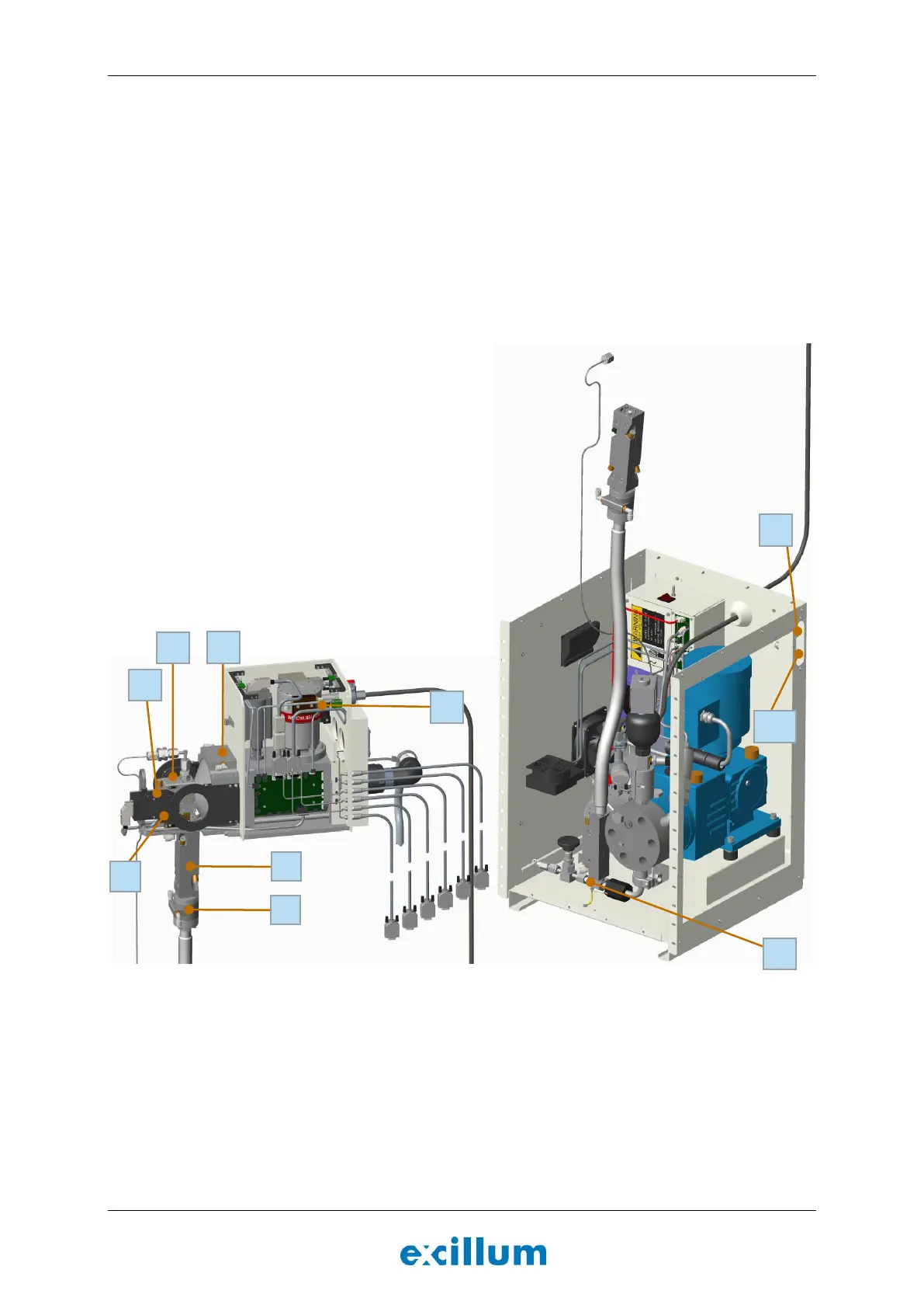
1. Pump box inlet
2. Turbopump cooling block
3. Lens cooling block
4. Electron dump cooling block
5. Blank window cooling block (when present)
6. Target chamber cooling
7. Upper cooling block
8. Jet brake cooling block
9. Lower cooling block
10. Pump box outlet
Figure 4-10. Cooling water flow direction through system subassemblies.
Follow the instructions below to connect the supply hose for the turbopump and the return hose from the
upper cooling block.
1. Remove the right-hand cover of the x-ray head, using a 2 mm Allen wrench, to expose the turbopump
cooling block and route the supply hose through the opening indicated in Figure 4-9. Connect the
water hose to the turbopump cooling block and make sure that it is properly connected.
Note: Leave the cover off until the pump motor has been started to ensure that there are no leaks.