MCS- 32/92 Digital Brushless AC servo drive system - Ref.0707
Pin Signal Function
1 A + A + signal
2 B + B + signal
3 Z + Z + signal
4 U - Phase switching U -
5 W - Phase switching W -
6 V - Phase switching V -
7 N.C.
Not connected
8 N.C.
9 N. C.
10 A - A - signal
11 B - B - signal
12 Z - Z - signal
13 U + Phase switching U +
14 W + Phase switching W +
15 V + Phase switching V +
16 N.C. Not connected
17 SELSEN1
Information of the installed
sensor given to the drive via
hardware
18 SELSEN2
19 + 485
RS-485 serial line for
SINCOS™ or SINCODER™
encoder
20 - 485
21 KTY -
Thermal sensor of the motor
22 KTY +
23 + 8 V
Voltage supply for SINCOS™
encoder or SINCODER™
24 + 5 V
Supply voltage for the
incremental encoder
25 GND 0 Volts
26 CHASSIS Pin
CHASSIS Screws
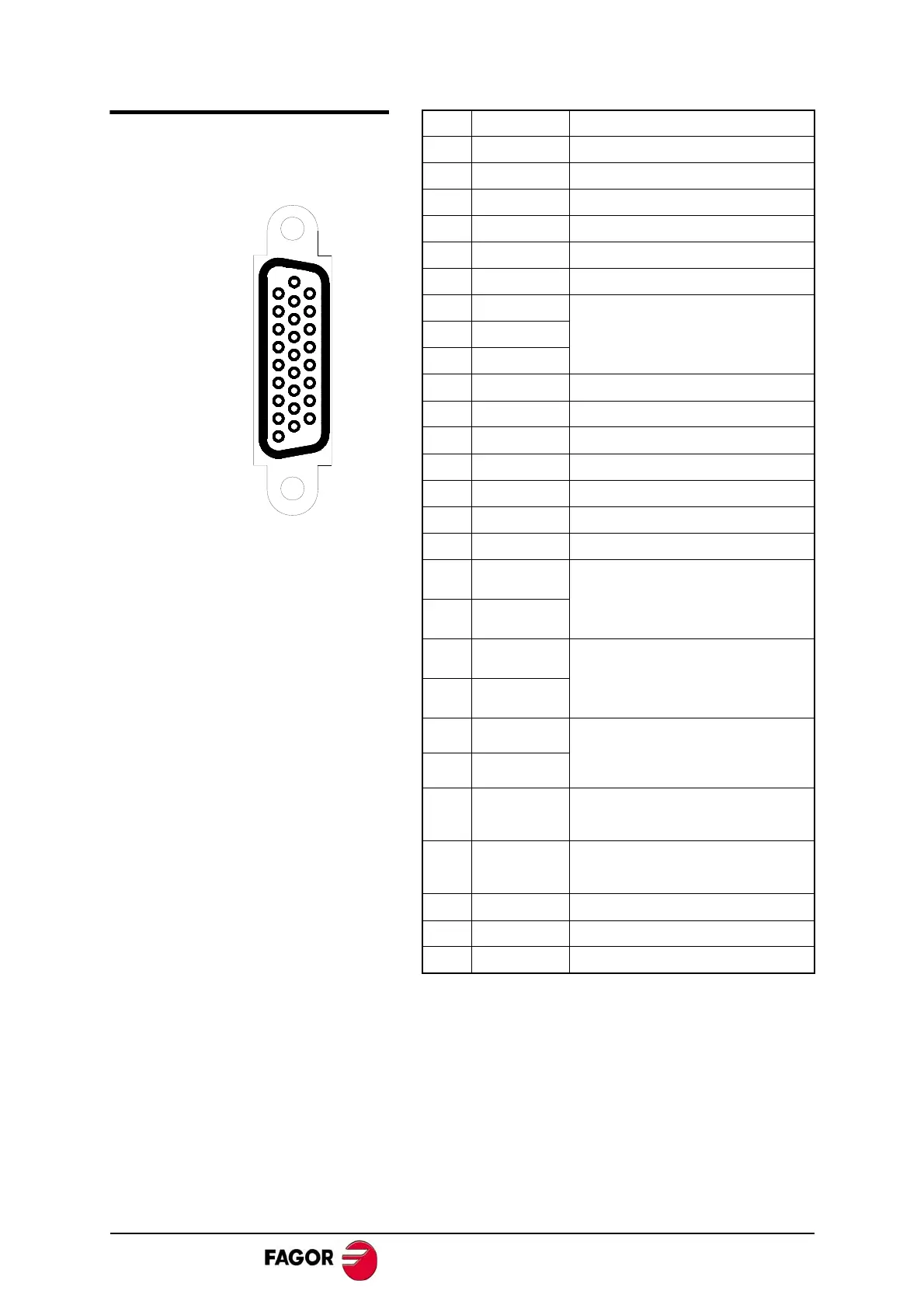
19
26
9
1
18
10
. INPUT CONNECTOR OF THE
OTOR FEEDBACK AND
EMPERATURE SENSOR
 Loading...
