74
(MT12 - Gb2004)
I
NTERCOMS *
V
IDEOINTERCOMS *
T
ELECOMMUNICATION
INTERNAL STATIONS
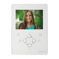
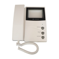
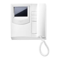
PT5660W. White colour videointercom with
traditional cathode tube with audio-video pri-
vacy, electronic microphone, differentiated
double electronic ringing sounds (modulated
and continuous note) and terminal board for the
connection to the wall-bracket. With two but-
tons, one for control switch ON and one for door
lock release, and 6 supplementary buttons, that
can be added for additional services such as:
control switch ON, intercommunicating calls,
stair lights, door lock release, etc. The buttons
are included in the kit of the videointercom. The
maximum acceptable current to the button ter-
minals is 60mA. For higher currents use relay
unit art.1471.
It can be installed on the wall by using the wall-
bracket art.WB5600 or WB5660 and the back-
box art. 1283. For particular needs it is possi-
ble to separate the common of the buttons
labelled P4, P5 and P6 by cutting the W1
jumper on the wall-bracket. The buttons have
the 2C terminal in common. In this case the
maximum acceptable current to the three but-
tons is 0.5A.
Technical data
Power Supply 18÷24Vdc
Operating current 0.6A
Video tube 4.5" - 90°
Television standard 625 lines
Horizontal frequency 15625Hz
Vertical frequency 50Hz
Bandwidth >5MHz
Video signal on 75Ω 0.8÷1.5Vpp
Starting up time 5÷7 sec.
Operating temperature 0°÷+50°C
Max. permissible humidity 90%RH
Videointercoms Project series
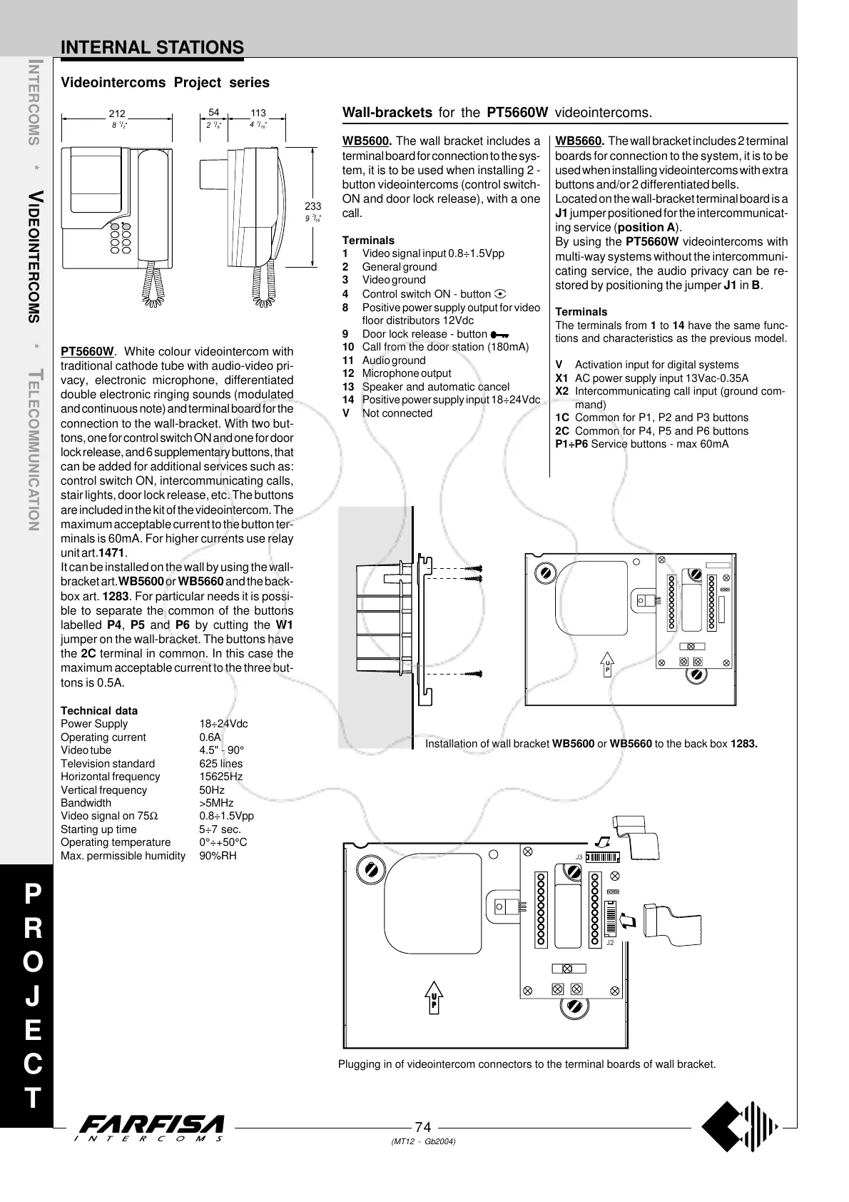
Installation of wall bracket WB5600 or WB5660 to the back box 1283.
U
P
Plugging in of videointercom connectors to the terminal boards of wall bracket.
Wall-brackets for the PT5660W videointercoms.
WB5600. The wall bracket includes a
terminal board for connection to the sys-
tem, it is to be used when installing 2 -
button videointercoms (control switch-
ON and door lock release), with a one
call.
Terminals
1 Video signal input 0.8÷1.5Vpp
2 General ground
3 Video ground
4 Control switch ON - button
8 Positive power supply output for video
floor distributors 12Vdc
9 Door lock release - button
10 Call from the door station (180mA)
11 Audio ground
12 Microphone output
13 Speaker and automatic cancel
14 Positive power supply input 18÷24Vdc
V Not connected
WB5660. The wall bracket includes 2 terminal
boards for connection to the system, it is to be
used when installing videointercoms with extra
buttons and/or 2 differentiated bells.
Located on the wall-bracket terminal board is a
J1 jumper positioned for the intercommunicat-
ing service (position A).
By using the PT5660W videointercoms with
multi-way systems without the intercommuni-
cating service, the audio privacy can be re-
stored by positioning the jumper J1 in B.
Terminals
The terminals from 1 to 14 have the same func-
tions and characteristics as the previous model.
V Activation input for digital systems
X1 AC power supply input 13Vac-0.35A
X2 Intercommunicating call input (ground com-
mand)
1C Common for P1, P2 and P3 buttons
2C Common for P4, P5 and P6 buttons
P1÷P6 Service buttons - max 60mA
P
R
O
J
E
C
T
233
9
"
16
/
3
212
54
82
""
28
//
11
113
4
"
16
/
7
6
5
2
1
4
3