30
OPERATION
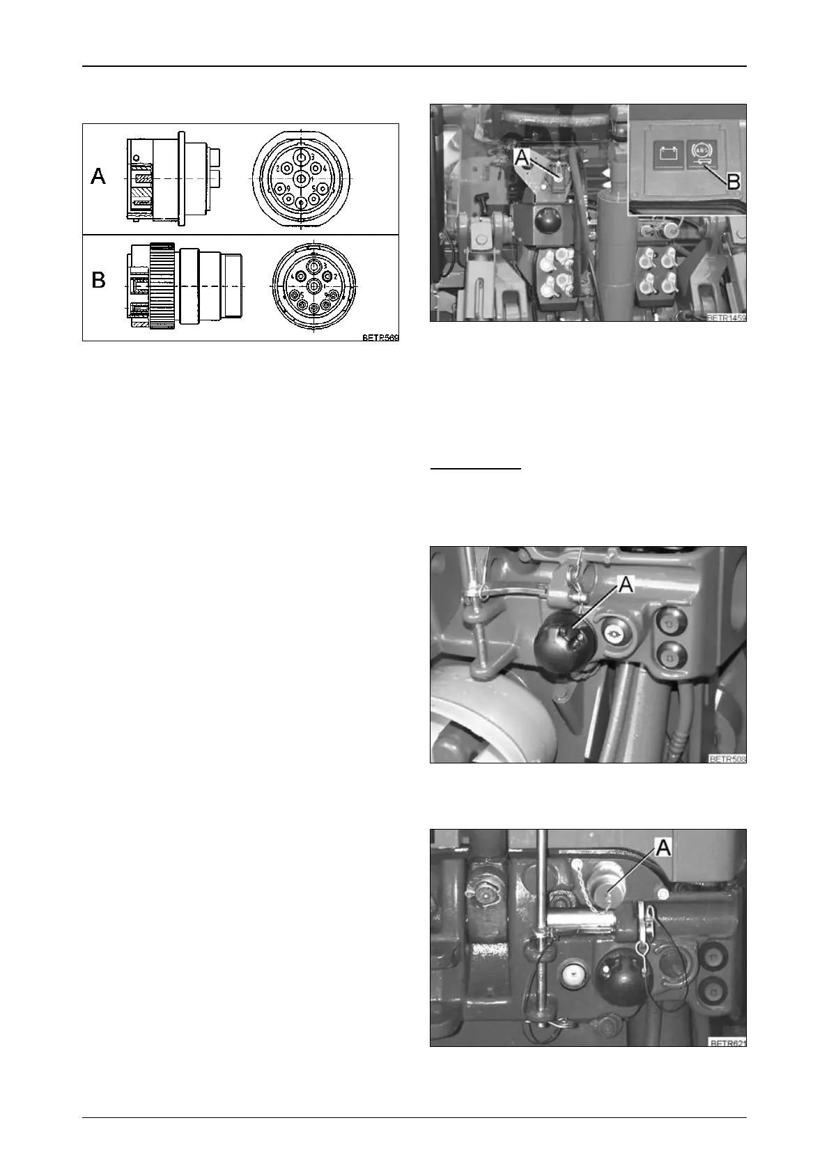
Pin - attribution LBS-ISO implement
socket rear and front
Operation_Pic_number:1
A = LBS-ISO socket for the mounted implement.
B = LBS-ISO connector for the mounted
implement.
Pin 1 = Earth 60A.
Pin 2 = Earth 25A.
Pin 3 = 60A power supply.
Pin 4 = 25A power supply for implement electro-
nics.
Pin 5 = Control signal for switching the end sy-
stem, bridged with pin 4 in the connector.
Pin 6 = CAN-EN.
Pin 7 = CAN GND.
Pin 8 = CAN High.
Pin 9 = CAN Low.
Fig.31
ABS socket (A)
Operation_Pic_number:1
1 = + UB 30
2 = + UB 15
3 = Earth electronics
4 = Earth tractor body
5 = Indicator lamp
IMPORTANT:
When turning the ignition ON or OFF, the in-
dicator lamp (B) in the instrument panel must
light up briefly for monitoring purposes.
Operation_Pic_number:1
Socket (A) at front (with front power lift only).
Operation_Pic_number:1
LBS-ISO socket (A) front (optional).
Fig.32
Fig.33
Fig.34
 Loading...