70
OPERATION
17.6 Setting the valves
Text-module
The following settings can be made:
ETNum-list
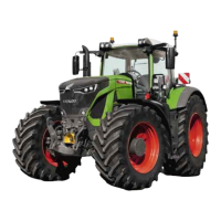
Opening the valve setting submenu
Operation_Pic_number:1
● Press key (F3). The following valve setting
submenu appears.
Operation_Pic_number:1
This window gives an overview of the individual
valve settings.
Text-module
● Indicator bars (A), lifting flow rate.
● Indicator bars (B), lowering flow rate.
● Indicator bars (C), activation period.
● Lock symbol (D), valve locking ON/OFF.
● Clock symbol (E), is displayed while the rele-
vant valve is activated by the time function.
● Cylinder symbol (F), is displayed while the re-
levant valve is activated in the floating posi-
tion.
● Valve prioritisation (H) appears if a valve is
prioritised.
● Keys (F1 - F4), for changing to the sub-menu
of individual valves.
1.Flow rate
2.Timer
3.Floating position
4.Valve locking
Fig.129
Fig.130
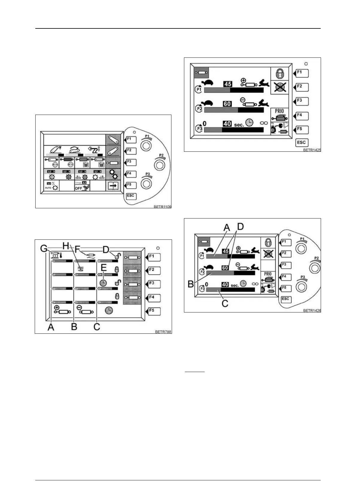
Example:
● Press key (F1). The following submenu appe-
ars.
Operation_Pic_number:1
● Use the ESC key to exit this submenu and se-
lect a different valve.
Setting the flow rate for lifting/lowe-
ring
(Setting range between 1-80 l/min).
Operation_Pic_number:1
Bar indicator (A), lifting.
Bar indicator (B), lowering.
● Set the flow rate for lifting with rotary switch
(P1), and for lowering with rotary switch (P2).
NOTE:
If only the bar indicator (A, B) changes and
the indicator (D) remains unchanged, the hy-
draulics are undersupplied. Increase engine
speed.
Fig.131
Fig.132
 Loading...