5.3 DIAGNOSIS VIA INTERBUS
The modular valve terminal offers the following
possibilities for diagnosis via INTERBUS:
• entries in the diagnostic register of the con-
troller board
• four status bits
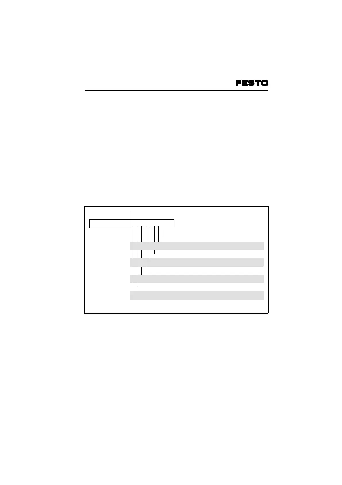
Diagnostic register (e.g. DCB module)
The diagnostic register of the controller board is
built up specifically for INTERBUS and contains
apart from other information the following diag-
nostic information:
n n + 1
707 6 5 4 3 2 1 0
USER User fault parametrizing
PF Periphery fault, e.g. valve terminal
BUS Bus fault
CTRL Fault in module/hardware
DETECT Diagnostic routine is active
RUN Diagnostic transmission is active
ACTIVE Selected configuration is ready to run
READY Module is ready to run
Fig. 5/7: Structure of diagnostic register
VIFB6 - 03/05 5. Diagnosis/Error Treatment
5-12
9809c