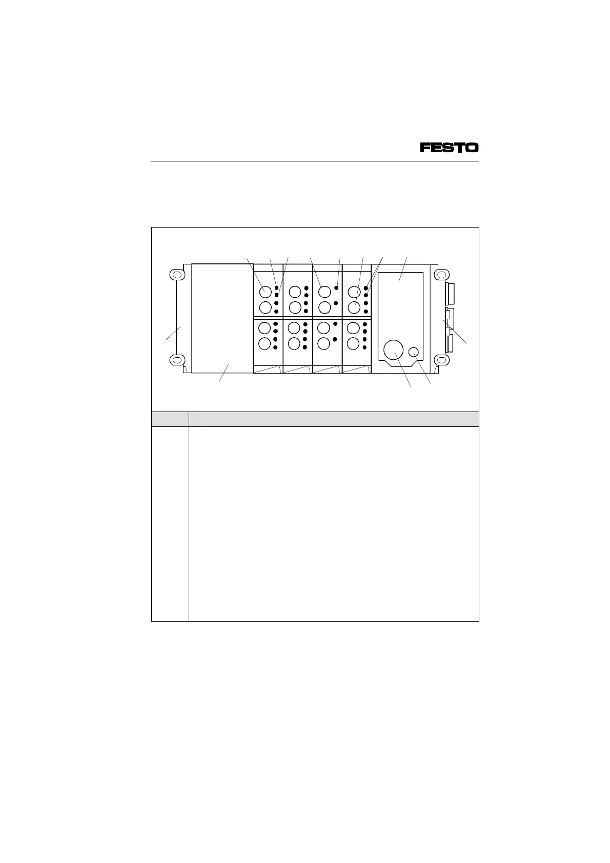
The following connection and display elements
are to be found on the electronic modules:
No. Meaning
1
2
3
4
5
6
7
8
9
10
11
12
13
Output socket for electronic output
Yellow LED (status display per output)
Red LED (error display per output)
Input socket for one electric input
Green LED (per input)
Input socket for two electric inputs
Two green LEDs (one LED per input)
Node with LEDs and field bus connection,
detailed description in Chapter "Installation"
Right-hand end plate
Fuse for internal inputs/sensors
Operating voltage connection
Additional I/O modules:
– Analogue I/Os
– AS-i master
– Additional power supply
– High current outputs (PNP or NPN)
– Multi I/O module 12I/8O (PNP or NPN)
Left-hand end plate
Fig. 1/2: Display and connection elements of the electronic modules
1011
12
234 5 6 7 8
9
O4 I4 I8
1
O4
13
VIFB6 - 03/05 1. System summary
1-4
9809c