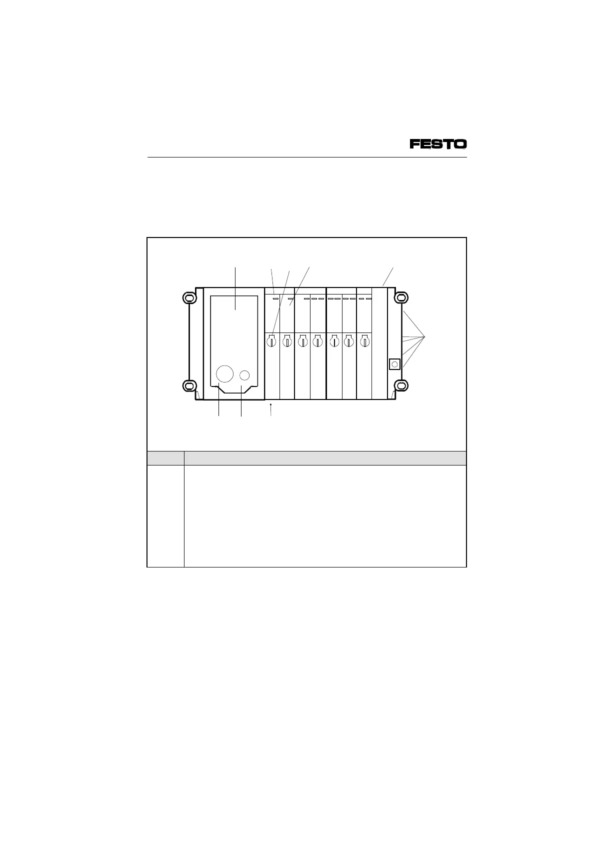
The following connection, display and operating
elements are to be found on the pneumatic MIDI
modules type 03:
No. Meaning
1
2
3
4
5
6
7
8
9
Node with LEDs and INTERBUS connection
further details in the chapter "Installation"
Yellow LEDs
Manual override for valve solenoid coils
Valve location inscription field
Unused valve location with cover plate
Common pneumatic tubing connections
Work connections (per valve)
Fuse for inputs/sensors
Power supply connection
2
3
4
9
8 7
51
Fig. 1/3: Operartion, display and connection elements of the pneumatic
VIFB6 - 03/05 1. System summary
9809c 1-5