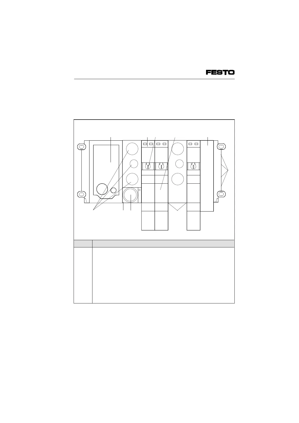
The following connection, display and operating
elements are to be found on the pneumatic
MAXI modules type 03:
No. Meaning
1
2
3
4
5
6
7
8
9
10
Node with LEDs and INTERBUS connection,
further details in the chapter "Installation"
Yellow LED (per valve solenoid coil)
Manual override (per valve solenoid coil)
Valve location inscription field (labels)
Unused valve location with cover plate
Common pneumatic tubing connections
Work connections (2 per valve, placed one obove the other)
Regulator for limitted pressure of auxiliary pilot air
Common pneumatic tubing connection
Exhausts
1
2
3
4
8
9
6
10
Fig. 1/4: Operartion, display and connection elements of the pneumatic
MAXI modules type 03
VIFB6 - 03/05 1. System summary
1-6
9809c
 Loading...


