6Functions
Festo – GDCP-CMMP-M0-FW-E N – 1304N H 57
For the cable, a screened line that twists together the data pairs A and A#, B and B#, N
and N# (twisted pairs) must be used. The outer screening must always be connected on
both sides to the motor the controller on the plug ho using. Only with the recommended
cable can reliable transmission with higher frequencies be ensured.
The 2nd displacement encoder must be act ivated in t he FCT. In paramet erisation, differentiation is
made between linear and rotative incremental encoders.
With linear measuring systems, the signal period, that is, the increment distance, is entered.
The real line count for rotative enc oders or the real resolution ( signal period) for linear encoders
must be paramete rised; this corresponds to the value before the quadrature evaluation.
For linear systems, in addition to the signal period, the reference signal (distance between two adjacent
zero-pulse signals) must be parameterised.
Through the selection of reversal of direction, the counting direction of the 2nd displacement encoder
can be turned. With activated encoder difference monitoring, th e permissible encoder difference is
specified in °.
The error E 171 (deviation between position actual value and commutation encoder too large) is output
if the ac tual position of the motor deviates by x° from the actual position of the external displacement
encode r. In particular for toothed belt axes, the value must not be selected too small, since an offset
always occ urs due to expansion of the toothed belt under load.
In the case of rotative incremental encoders, it is not the signal period, but the line c ount per revolution
of the external encoder that is specified. In addition, a transmission ratio (standard 1:1) can be con-
figured. The line count always refers to one revolution of the motor.
With the values to be entered here for an “electronic gear unit”, the transmission ratio between the
commutation encoder (in the motor) and the 2nd encoder as position enc oder is compensated for.
Enter here the inverse of the multiplic ative product of the gear unit present between the two encoders.
All other parameters must be set as with the linear system.
6.6.7 EGC-...-M at [X10]
For EGC axes with type code –M, an incremental displacement encoder is already attached.
The sensor of the 2nd displacement encoder of an EGC-…-M axis has the following technical data:
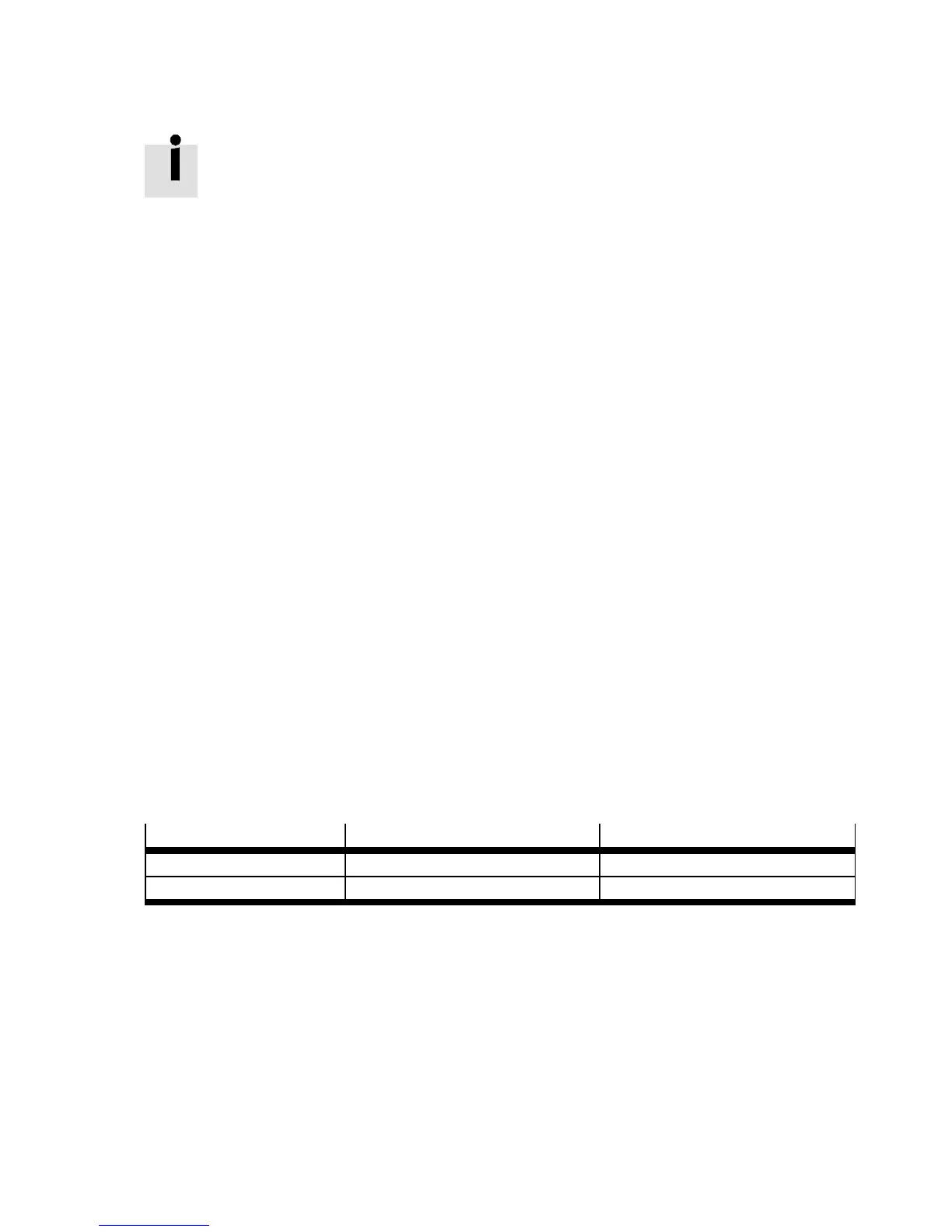
Axis
Signal period Reference signal
EGC-...-M1 [mm] 0.01 5
EGC-...-M2 [mm] 0.04 5
Tab. 6.21 Signal period EGC
As par t of the normal parameterisation, the 2nd displacement enc oder must be activated.
Through the selection of reversal of direction, the counting direction of the 2nd displacement encoder
can be t urned.
Parameters to be set:
– Signal period ( Tab. 6.21)
– Encoder difference
– Reference signal
The encoder difference of 60° represents a st art value that is operational in most cases. But it must be
adjusted, depending on the application.

 Loading...