7 D ynamic response
Festo – GDCP-CMMP-M0-FW-E N – 1304N H 75
7.1.2 Behaviour under normal operation and control properties
In operation, the power consumption of the motor controller from the mains network is monitored via
the PFC step. The mains current is regulated by an analogue control circuit so that the shape of the
curve reflects that of the mains voltage sinewave and the phase shift is 0°. The amplitude is adjusted
according to the specified effective power.
A higher-level digital controller regulates the intermediate circuit voltage to an average v alue of approx.
360 V DC. To relieve the relatively sluggish voltage regulation under load changes (acc eleration/braking
of the drive), the effective power delivered to the motor from the motor c ontroller is measured and
used to pre-control the PFC step.
100V … 230 V AC
±10
F
L
D
T8
C
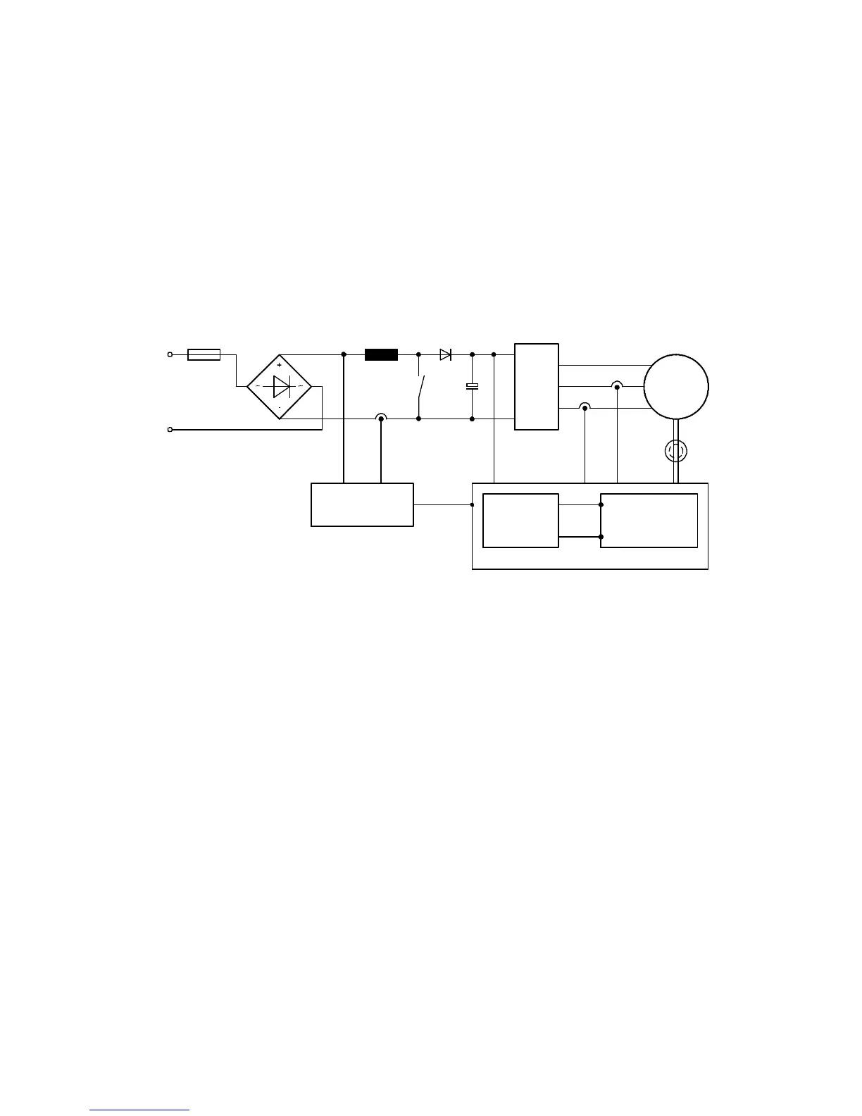
U_in I_in U_ZK i_u i_v Angle encoder
3~
PWM
M
3~
PWM
IC for Power
Factor Control
Voltage
regulator
Drive
regulator
u_q
i_q
Microcontroller
Fig. 7.1 Schematic structure of the PFC step
Control encompasses the following variables:
– Digital c ontrol of the intermediate circuit voltage to an average of approx. 380 V DC
– Analogue c ontrol of the mains input current
– Maintenance of a sine-wave mains current under stationary load conditions
– Operation with cosü 0.97 at rated operation (at the rated output of the PFC step)
The parameterisation program can be used to switch the PFC c ontrol on or off. When the PFC is deac-
tivated, the intermediate circuit behaves like a normal intermediate circuit with an upstream bridge
rectifier.
The intermediate circuit voltage is usually regulated to a constant average value tha t, under stationary
load c onditions, is independent of the specified effective power of the motor.

 Loading...